FM25B • 11
Inductors
1 Shielded can inductor, 0.18 uH [L1]
2 Pre-wound spring style inductors, 44 nH [L2,4]
2 1 µH axial inductors (brown-black-gold) [L3,5]
Hardware, Misc.
1 PIC 16C505 microcontroller IC (marked with white sticker) [U2]
1 BH1415F Stereo generator IC [U3] Preinstalled!
NOTE: These surface mount parts may be pre-installed on your circuit board.
Check the solder side of the PC board for these parts.
1 7.6 MHz crystal (thin shiny rectangle marked 7.600000) [X1]
1 78L05 +5 volt voltage regulator [VR1]
1 14-pin socket for U2
1 LM358 Low Power Dual Operational Amplifier IC [U1]
1 GAL5 SMT Amplifier IC (surface mount chip with 4 leads, 3 on one
side) [U4] Preinstalled!
1 Two pin jumper and jumper block [J1]
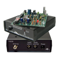
1 ‘F’ type board mount connector [J3]
2 3.5mm stereo jacks [J4,5]
1 2.1mm DC power jack [J2]
1 DPDT push-button switch [S4]
3 DIP switches (8 pin dip with 4 sliding tabs) [S1,2,3]
1 Whip antenna [ANT1]
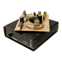
1 FM25B printed circuit board
1 1/8” stereo to RCA cable
1 AC125 12 volt DC power transformer
Required, not supplied
Line level audio source (such as a tape deck or CD player)
Case and Knob Parts
Top cover with drilled antenna hole
Bottom base tray
4 - Short Phillips Head Screws
2 - Long Phillips Screws
Front and Rear Plastic Panels
Front and Rear Labels
4 - Rubber Feet
Appropriate Knobs for Kit
Required Tools
Small Phillips Head Screwdriver
Pen or Pencil
Sharp hobby knife or hand held paper punch
Ruler at least 6 inches long
Multimeter for voltage adjustment