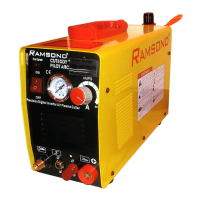
The Ramsond CUT 50/70 DY Series is a digital inverter air plasma cutter designed for air plasma cutting and gouging. This dual-voltage machine operates on either 110V or 220V, automatically detecting the input voltage without requiring a manual switch. For 110V operation, a NEMA 30 Amp outlet and a 30 Amp circuit are required, while 220V operation requires a 20 Amp circuit. The unit is not equipped with a standard wall plug to accommodate these different configurations.
Function Description:
The plasma cutter works by sending pressurized air through a small channel containing a negatively charged electrode. When power is applied and the nozzle tip touches the metal, a circuit is created, generating a powerful spark between the electrode and the metal. As inert gas (compressed air) passes through the channel, the spark heats the gas to its fourth state of matter, creating a stream of directed plasma. This plasma, reaching temperatures of approximately 30,000°F and moving at 20,000 feet per second, vaporizes metal and molten slag. The plasma itself conducts electrical current, and the arc is continuous as long as power is supplied and the plasma remains in contact with the metal being cut. The cutter nozzle also features a second set of channels that release a constant flow of shielding gas around the cutting area, which controls the radius of the plasma beam. The machine is designed to use only compressed air as the "gas."
Important Technical Specifications:
- Models: CUT 50/70 DY Series
- Processes: Air Plasma Cutting and Gouging
- Power: DC 1 Phase
- Voltage: Automatic Dual Voltage 110V / 220V
- Current Draw: Requires a 30 Amp circuit for 110V operation and a 20 Amp circuit for 220V operation.
- Air Pressure: The air regulator adjusts pressure to desired levels, typically between 20-60 PSI.
- Duty Cycle: The unit has internal duty cycle overload protection. At full power, it can cut for 6 minutes and then requires 4 minutes to cool down. Exceeding the duty cycle can damage the unit and void the warranty.
- Thermal Protection: Thermal protection circuits engage if the unit exceeds its duty cycle, stopping operation until the unit cools down to an acceptable temperature. The cooling fan continues to run during this period.
- Voltage Regulation: An Automatic Voltage Compensation Circuit prevents voltage load from exceeding maximum limits, extending the machine's life.
Usage Features:
- Front Panel Controls:
- Foldable Handle: For portability.
- Pressure Gauge: Displays air pressure.
- Digital Display: Shows current (Amps). It includes a calibration screw for adjustment if the display is out of range.
- ON/OFF Switch: Powers the unit on and off. The digital display may remain lit for up to 1 minute after shutdown, which is normal.
- Current Adjustment Knob: Adjusts the amperage output.
- Torch Control Connection: For the electrical connection of the plasma torch.
- Torch Air/Gas Connection: For the air hose of the plasma torch.
- Ground Clamp Connection: For the ground clamp.
- Air Intake Vents: For cooling.
- Back Panel Connections:
- Air Compressor In: Connects to the air compressor.
- Air Line to Gauge: Ensures the airline is firmly installed.
- Pressure Regulator: Adjusts air pressure. An arrow indicates the proper installation direction.
- Air In: Filter screen should be free from debris.
- Fan: For cooling.
- Power Cable: The main power cable consists of 3 wires: Brown or Red (Line), Blue or Black (Neutral), and Two-Tone Green/Yellow (Ground).
- Air Regulator/Filter: Adjusts air pressure and removes moisture from compressed air. It attaches to the rear of the unit, with connections for the compressor and the plasma torch. The adjustment knob on top adjusts air pressure. Collected moisture can be drained by pulling the WATER DRAIN RELEASE.
- Plasma Torch: Consists of a cup, tip, swirl ring, and reversible electrode. The unit comes with consumables including cups, swirl rings, tips, reversible electrodes, and O-rings.
- Ground Clamp: Must be firmly installed on the workpiece, ensuring good metal-to-metal contact and cleanliness (free from debris, rust, and dirt). It should be clamped to a part of the workpiece that is NOT being cut off.
- Operation Modes:
- Drag Cutting: Position the torch tip slightly above the workpiece, press the torch switch, and lower the tip until contact is made and the cutting arc is established. Move the torch in the desired direction, keeping the tip slightly angled and in contact with the workpiece. Maintain spark concentration under the workpiece; if sparks radiate above, the torch is moving too fast.
- Stand-Off Cutting: Raise the torch tip between 1/16" and 1/8" above the workpiece. This method can be used for penetration, gouging, or cutting sheet metal to reduce splatter-back tip damage.
- Piercing: Position the tip approximately 1/8" above the workpiece, angle the torch slightly to direct sparks away from the operator. Initiate the arc and lower the tip until the main cutting arc transfers. Start the pierce off the cutting line on a scrap piece or template, then continue the cut onto the cutting line. Hold the torch perpendicular to the workpiece after piercing.
- Safety Precautions: The manual emphasizes reading all safety precautions before use, including warnings about electric shock, moving parts, hot parts, fire/explosion hazards, fumes/gases, noise, arc rays, exploding parts, and EMF information. It also includes California Proposition 65 warnings.
Maintenance Features:
- After Each Use:
- Clean and inspect the torch cup, tip, swirl ring, and reversible electrode. Ensure the unit is disconnected from the power source and has cooled down.
- Replace consumables when needed.
- Inspect the air regulator and pressure gauge.
- Every 3 Months of Use:
- Service the air regulator/filter.
- Inspect labels for readability.
- Inspect air hoses and cables for cracks or breaks.
- Inspect the torch handle and consumables.
- Replace any worn or broken parts.
- Every 6 Months of Use:
- Service the air regulator (listed twice, likely an error in the original document).
- Inspect labels for readability.
- Inspect air hoses and cables for cracks or breaks.
- Inspect the torch handle and consumables.
- Vacuum out air vents and fan.
- General Maintenance: Always turn off the unit and disconnect it from the power source before any service or inspection. Allow the unit to cool down. Turn off the unit before draining water from the air regulator filter to prevent water from being sucked into the unit by the fan. Ensure proper installation of regulator fittings by following the arrow direction for air flow, as incorrect installation will substantially affect performance. Before each use, inspect the power cable for breaks, cuts, or defects; do not use if defective.
Operating Environment:
- The unit can operate in environments with temperatures between -10°C and +40°C and a maximum humidity level of 80%.
- Do not use the machine in wet or raining conditions; keep it dry and prevent water from entering.
- Do not use in environments with high concentrations of dust or corrosive gas.