:=1
-,r,
ILl
sl
II
5';
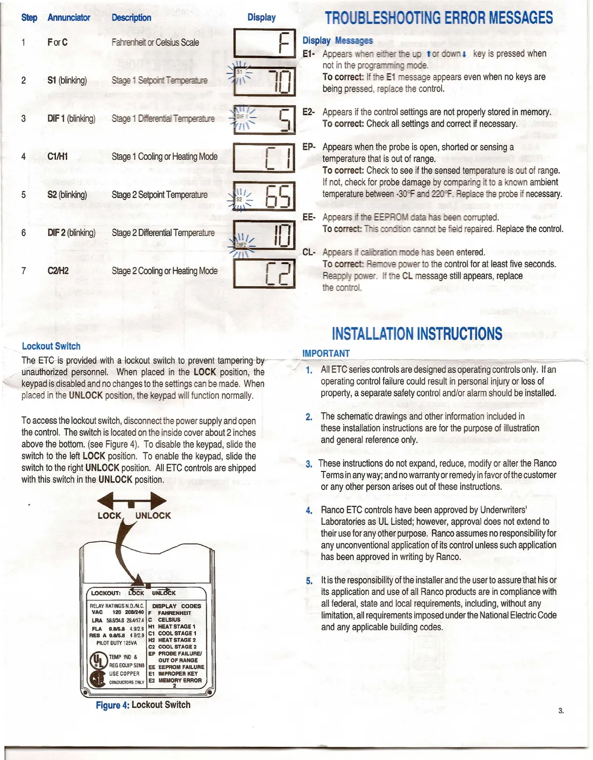
Lockout Switch
~ 8~is provieJed with -a-lockotJt switch to prevent-tampering--b
unauthorized personnel. When placed in the LOCK position, the
keypad is disabled and no changes to the settings can be made. When
placed in the UNLOCK position, the keypad will function normally.
To access the lockout switch, disconnect the power supply and open
the control. The switch is located on the inside cover about 2 inches
above the bottom. (see Figure 4). To disable the keypad, slide the
switch to the left LOCK position. To enable the keypad, slide the
switch to the right UNLOCK position. All ETC controls are shipped
with this switch in the UNLOCK position.
~
LOCK UNLOCK
RELAYRATINGSN.O.IN.C. DISPLAY CODES
VAC 120 2081240 F FAHRENHEIT
LRA 58N.l4.8 29.4117.4C CELSIUS
FLA 9.815.8 4.912.9 HI HEAT STAGE 1
RES A 9.815.8 4.9/2.9 Cl COOL STAGE 1
PILOTOUTY125VA H2 HEAT STAGE 2
C2 COOL STAGE 2
f
TEMP INO
&
EP PROBE FAILUREI
OUT OF RANGE
•• REGEQUIP52N8 EE EEPROM FAILURE
USECOPPER E1 IMPROPER KEY
CONDUCTORS
ONLYE2 MEMO:Y ERROR
•
TROUBLESHOOTING ERROR MESSAGES
Display essa es
E1· Appears , "
t!
ey is pressed when
not in the pr e.
To correct: If e E1 essage appears even when no keys are
being pressed, replace the control.
E2· Appears if the control settings are not properly stored in memory.
To correct: Check all settings and correct if necessary.
Ep· Appears when the probe is open, shorted or sensing a
temperature that is out of range.
To correct: Check to see if the sensed temperature is out of range.
If not, check for probe damage by comp . g' a own ambient
temperature between
-30Of .
e
c::.
e probe if necessary.
rrupted.
repaired. Replace the control.
e as been entered.
er to the control for at least five seconds.
. I e CL message still appears, replace
INSTALLATION INSTRUCTIONS
IMPORTANT
----
1. All ETC series controls are designed as operating controls only. If an
operating control failure could result in personal injury or loss of
property, a separate safety control and/or alarm should be installed.
2. The schematic drawings and other information included in
these installation instructions are for the purpose of illustration
and general reference only.
3. These instructions do not expand, reduce, modify or alter the Ranco
Terms in any way; and no warranty or remedy in favor of the customer
or any other person arises out of these instructions.
4. Ranco ETC controls have been approved by Underwriters'
Laboratories as UL Listed; however, approval does not extend to
their use for any other purpose. Ranco assumes no responsibility for
any unconventional application of its control unless such application
has been approved in writing by Ranco.
5. It is the responsibility of the installer and the user to assure that his or
its application and use of all Ranco products are in compliance with
all federal, state and local requirements, including, without any
limitation, all requirements imposed under the National Electric Code
and any applicable building codes.

 Loading...