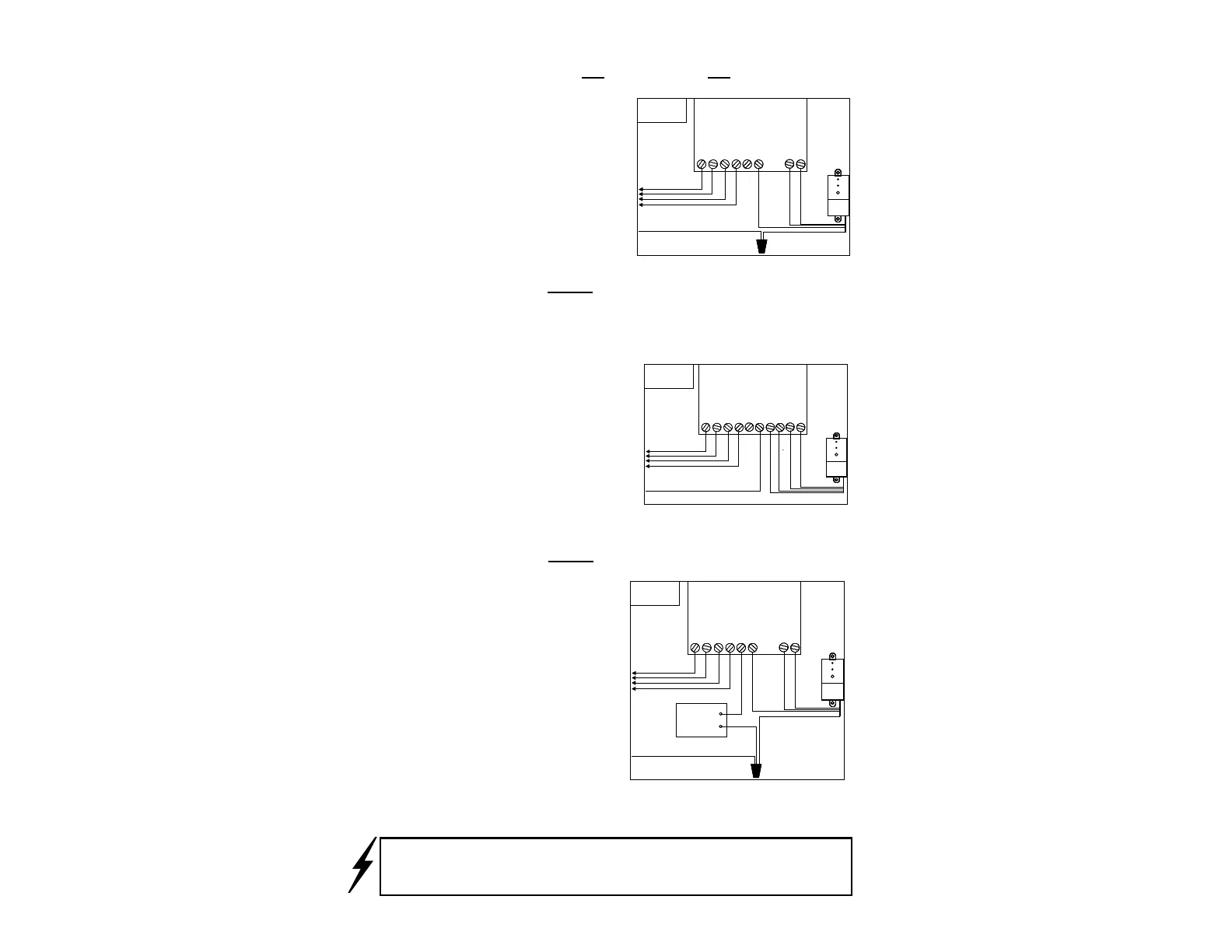
A. Controllers with NO Sensor Inputs, NO Pump Start or
Master Valve: (Fig. 3)
Disconnect the common con-
trol wire from the common
terminal of the controller.
Join this wire to the White
Receiver control wire using a
wire nut. Attach the Brown
control wire (N/C) to the
common terminal on the con-
troller.
B. Controllers WITH Sensor Inputs: (Fig. 4)
Find the controller terminals marked “Sensor” or “SEN” and
directly connect the White & Brown wires to these two termi-
nals, in any order. There may be a jumper tab or wire that must
be removed from between the
terminals, or a “sensor con-
nected” switch that must be
activated. Note: If the con-
troller requires a Normally
Open sensor circuit (such as
the Toro Greenkeeper
TM
or
Toro ECx
TM
), attach the White
and Green wires to the termi-
nals.
C. Controllers WITH Pump Start or Master Valve: (Fig. 5)
Similar to Step A, discon-
nect All the common control
wires from the common ter-
minal(s) of the controller.
Join these wires to the
White Receiver control wire
using a wire nut. Be sure to
include the common wire
from the Pump Start Relay
with these. Next attach the
Brown Receiver control
wire to the common termi-
nal on the controller.
Step 2. Power Wires (low voltage):
1 2 3 4
Valve
Terminals
To Valves
Common From Valves
White
Yellow*
Valve Controller / Timer
Pump / MV
24 VAC
24 VAC
Black
Red
S
S
C
* Use Green wire (in place of Yellow) if a normally open circuit is required
1 2 3 4
Valve
Terminals
To Valves
Common From Valves
White
Yellow*
Valve Controller / Timer
Pump / MVPump / MV
24 VAC24 VAC
24 VAC24 VAC
Black
Red
SS
SS
CC
* Use Green wire (in place of Yellow) if a normally open circuit is required
Fig. 4
!
1 2 3 4
Valve
Terminals
To Valves
Common From Valves
White
Yellow
Wire Nut
Valve Controller / Timer
Pump / MV
24 VAC
24 VAC
Black
Red
C1 2 3 4
Valve
Terminals
To Valves
Common From Valves
White
Yellow
Wire Nut
Valve Controller / Timer
Pump / MVPump / MV
24 VAC24 VAC
24 VAC24 VAC
Black
Red
CC
Fig. 3
Brown
Brown
1 2 3 4
Valve
Terminals
To Valves
Common From Valves
White
Yellow
Wire Nut
Valve Controller / Timer
Pump / MV
C
24 VAC
24 VAC
Black
Red
Pump
Start
Relay
1 2 3 4
Valve
Terminals
To Valves
Common From Valves
White
Yellow
Wire Nut
Valve Controller / Timer
Pump / MVPump / MV
CC
24 VAC24 VAC
24 VAC24 VAC
Black
Red
Pump
Start
Relay
Pump
Start
Relay
Fig. 5
Brown
Brown) *Use Green wire (in place of Brown) if a normally open circuit is required.
IMPORTANT: Do NOT connect the Receiver directly to 120/240VAC
as this will result in irreversible damage. If you are in doubt, contact a
qualified installer or electrician.
3
 Loading...