OPERATION:
Normal Operation:
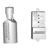
When the Wireless RainSensor activates due to sufficient rainfall, the
“System Off - Rain” light will remain illuminated on the Receiver. After
the rain sensor “dries out”, the controller will resume its normal watering
schedule.
Smart Bypass
TM
:
Your Wireless RainSensor can be temporarily deactivated by using the
built in Smart Bypass button. Simply tap this switch once and the
“System Off - Rain” light will go out until the next time the Wireless
RainSensor resets - all automatically.
Battery Low Indicator:
When the “Battery Low” indicator light illuminates constantly, it serves
as a warning that the Transmitter’s battery is getting low and it should be
replaced when convenient. The Wireless RainSensor will function prop-
erly for some time after this indicator is present. Note: A brief “Battery
Low” light illumination is used to indicate a valid transmission from the
Transmitter. This is a diagnostic tool and does not indicate that the bat-
tery is low.
Battery Replacement: To replace the batteries, simply remove the Trans-
mitter from the bracket, slide the bottom from the housing by first de-
pressing the two opposing clips, and gently pull the circuit board out of
the unit. Replace using two 3V CR2032 cells or equivalent, paying close
attention to polarity (+/-).
CODE CHANGING:
The transmission code for the unit is identified by stickers on the Trans-
mitter & Receiver. Although, in most cases, even if two identical units
are installed, unwanted activations would only occur if the two sensors
are set for different rainfall amounts.
However, the code may be manually changed as follows:
1. Remove the Transmitter’s Bottom cover by pressing the tabs in and
slide the circuit board out.
2. Identify the code wire loops (black and white small loops) & cut one
or both wires with end cutting pliers.
3. Disconnect the power from the Receiver and remove the cover.
4. Cut the SAME colored wire(s) as was done for the Transmitter.
5. Re-assemble and test the operation.
6
 Loading...