QUICK START INSTRUCTIONS:
For the experienced installer, the following instructions can be used.
1. Mount Receiver adjacent to controller with screws provided.
2. Turn off or disconnect power to the timer/controller.
3. Attach Receiver control wires to the sensor inputs OR
a. Disconnect common valve wire and common pump/master
valve wire, if present.
b. Attach white wire to common wire(s).
c. Attach brown wire to common terminal on controller.
4. Connect the red & black Receiver wires to the controller’s low volt-
age power source (24V)
5. Test wiring by pressing & holding the Transmitter spindle.
6. Adjust Transmitter cap to desired activation rainfall amount.
7. Mount Transmitter in an unobstructed location away from sprinklers.
8. Re-confirm operation of Transmitter at mounting location.
** DETAILED INSTALLATION INSTRUCTIONS **
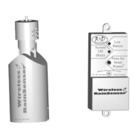
There are two main components,
the Transmitter and the Receiver.
The Transmitter is installed out-
doors where it is exposed to all
rainfall. The Receiver is installed
in a weatherproof location adjacent
to the sprinkler valve controller.
Install the Receiver first, at a loca-
tion in close proximity to the irri-
gation controller. Extend the An-
tenna straight up. (See Fig. 2).
WIRING THE RECEIVER: (TWO STEPS INVOLVED)
There are two steps involved:
Step 1: Attach the control wires
Step 2: Attach the low voltage power wires
Step 1. Control Wires (Disconnect power to the Controller):
The Receiver control wires (White, Brown, and Green) are used to inter-
rupt the common wire of the valves or they can be hooked up directly to
the sensor input of the controller itself, if present.
Antenna
5 conductor wire
Valve Controller / Timer
Receiver
Antenna
5 conductor wire
Valve Controller / Timer
Receiver
Fig. 2
2