Instrument Tour
R&S
®
RTC1000
16Getting Started 1335.7346.02 ─ 06
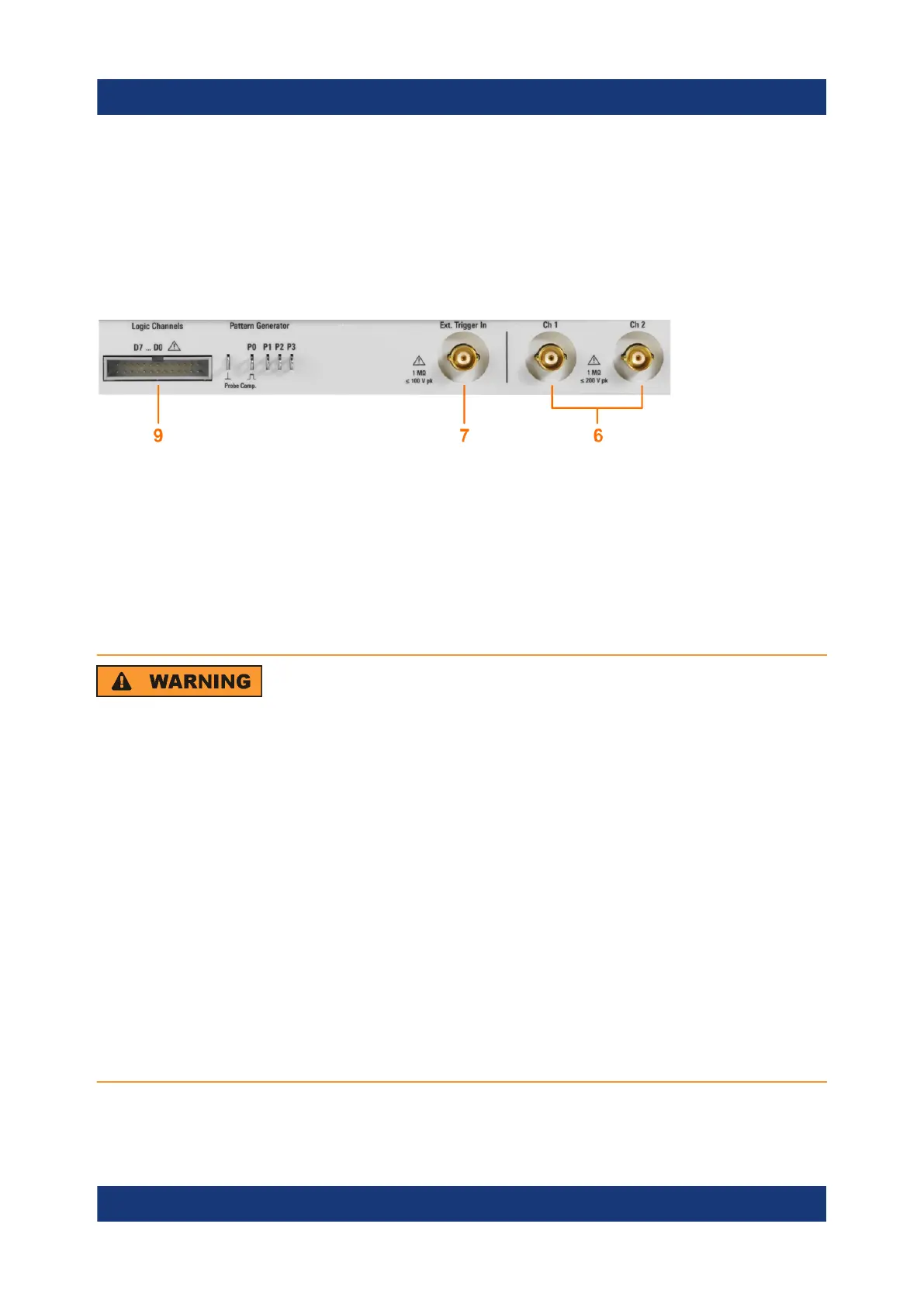
9 = Connector for the logic probe (option R&S RTC-B1)
10 = Multi-purpose BNC connector [Aux Out]
11 = USB connector
4.1.1 Input Connectors
BNC inputs (6, 7)
The R&S RTC1000 has two channel inputs (6) to connect the input signals. The
external trigger input (7) is used to control the measurement by an external sig-
nal. The trigger level can be set from -5 V to 5 V.
The input impedance of all BNC inputs is 1 MΩ.
Risk of electrical shock - maximum input voltages
The maximum input voltage on channel inputs must not exceed
200 V (peak) and 150 V (RMS).
For the external trigger input, the maximum input voltage is 100 V (peak)
and 70 V (RMS).
Transient overvoltages must not exceed 200 V (peak).
Voltages higher than 30 V (RMS) or 42 V (peak) or 60 V DC are regarded
as hazardous contact voltages. When working with hazardous contact vol-
tages, use appropriate protective measures to preclude direct contact with
the measurement setup:
●
Use only insulated voltage probes, test leads and adapters.
●
Do not touch voltages higher than 30 V (RMS) or 42 V (peak) or
60 V DC.
Front Panel