EasyManua.ls Logo

Rane AC 23 User Manual

Rane AC 23
18 pages
To Next Page IconTo Next Page
Page #1 background imageLoading...
Page #1 background image
Manual-1
AC 23
ACTIVE CROSSOVER
OPERATORS MANUAL
AC 23 CONNECTION
Balanced/Unbalanced Inputs
The ¼" Input jacks on the AC 23 are TRS (tip-ring-
sleeve). We recommend connecting the AC 23 with a bal-
anced cable from the balanced output of a mixer or equalizer.
If a balanced output is not available, and the cable run is
less than ten feet (three meters), inserting an unbalanced ¼"
TS (tip-sleeve) plug works in most situations.
Unbalanced Outputs
The ¼" Output jacks on the AC 23 are unbalanced TS
(tip-sleeve). We recommend that cables to the amplifiers be
no longer than ten feet (three meters).
See the “Sound System Interconnection” RaneNote
included with this manual for more information on cabling
and grounding requirements.
QUICK START
This is an automatic crossover! By automatic, we mean that the AC 23 is smart enough to know whether you want to
run it as a two channel crossover, or as a single channel unit. It knows by the way the plugs are inserted how your system is
to be configured. However, just because it is automatic, doesn’t mean that it will not automatically confuse you when you
try to connect it in a bench test situation. Note: Labels above the controls refer to the unit being operated in the 2- or 3-
Way Stereo mode. Labels below the controls refer to the unit being operated in the 4- or 5-Way Mono mode.
Plugging a signal into the CHANNEL 1 INPUT and nothing into the CHANNEL 2 INPUT tells the unit that you are
running a single channel system in Mono 4- or 5-Way mode, and therefore sets the unit up to be a single channel device.
This can lead one to think that there are some dead channels in the unit when looking for output in places where there
shouldn’t be any. The even more automatically confusing part is the way that the Output connectors decide whether the unit
is a 4-Way or 5-Way crossover. It is actually rather straightforward.
To test the unit as a Mono 4-Way, first slide the CHANNEL 1 and 2 switches on the back to 3-WAY. Connect the
INPUT source to CHANNEL 1 only. Following the labels below the jacks, look at SUB OUT, then look at LOW OUT,
now go back to MID OUT, and then proceed to the HIGH OUT. So far, so good.
To test the AC 23 as a Mono 5-Way, the only precaution required is there must be a “dummy” plug (¼" unconnected
plug) inserted into the HI MID OUT to program the crossover properly. When you reach the point where you want to
measure the output of the channel with the dummy in it, simply remove it and insert your test output plug in that location.
When operating the AC 23 as a Stereo 3-Way, follow the diagram on page Manual-5, reading the labels above the jacks
and controls. To drive both Channels with a mono signal, connect only to the CHANNEL 2 INPUT. This approach is the
same as if you used a wye cable to both Inputs.
The AC 23B is available as a fully balanced output version equipped with XLR connectors (for inputs and outputs)
instead of the ¼" jacks. If you are connecting to balanced amplifiers from the AC 23 or are running crossover output cable
lengths greater than 10 feet (or 3 meters), we highly recommmend you purchase an AC 23B.
Never connect anything except an RS 1 or other approved Rane AC power supply to the thing that looks like a
telephone jack on the rear. This is an 18 VAC center-tapped power unit. Consult the Rane factory for replacement or
substitution.
WEAR PARTS: This product contains no wear parts.

Other manuals for Rane AC 23

Question and Answer IconNeed help?

Do you have a question about the Rane AC 23 and is the answer not in the manual?

Rane AC 23 Specifications

General IconGeneral
Frequency Range20 Hz - 20 kHz
Slope12 dB/octave
Input ConnectorsXLR, 1/4" TRS
Output ConnectorsXLR, 1/4" TRS
Signal to Noise Ratio> 100 dB
Input Impedance20 kΩ
Output Impedance100 Ω
Maximum Input Level+22 dBu
Maximum Output Level+22 dBu
Power Supply100-240 VAC, 50-60 Hz
Power Consumption15 W
Dimensions19" x 1.75"
Configuration2-way

Summary

QUICK START Guide

Automatic Crossover Operation

Explains how the AC 23 automatically configures based on input connections for 2/3/4/5-way modes.

AC 23 CONNECTION

FRONT PANEL: STEREO 2-WAY CONFIGURATION

Channel 1 Front Panel Controls

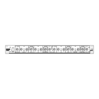
Details controls for Channel 1: MASTER LEVEL, LOW LEVEL, LOW MUTE, LOW DELAY, LOW/HIGH crossover selector.

REAR PANEL: STEREO 2-WAY INSTALLATION

FRONT PANEL: STEREO 3-WAY CONFIGURATION

Channel 1 Controls Overview

Details controls for Channel 1: MASTER LEVEL, LOW LEVEL, LOW MUTE, LOW DELAY, LOW/MID crossover, MID LEVEL, MUTE, DELAY, MID/HIGH crossover, HIGH LEVEL.

REAR PANEL: STEREO 3-WAY INSTALLATION

FRONT PANEL: MONO 4-WAY AND 5-WAY CONFIGURATION

IMPORTANT NOTE

CHASSIS GROUNDING Procedures

Provides detailed steps and recommendations for grounding the chassis to avoid hum and buzzing.

REAR PANEL: MONO 4-WAY AND 5-WAY INSTALLATION

REAR PANEL: ALTERNATE MONO 4-WAY INSTALLATION

Alternate Mono 4-Way Mode Warning

Warns about potential oscillation if Channel 1 input is unconnected in this mode.

Plugging/Unplugging Patch Cord Caution

Cautions against plugging/unplugging with power on due to potential speaker damage.

OPERATING INSTRUCTIONS

Selecting Crossover Frequencies

Guides on selecting crossover frequencies, considering driver specs and detent accuracy.

Time Delay Adjustment Necessity

Explains the necessity and basic effects of time delay for phase alignment of drivers.

Time Delay Adjustment Using Realtime Analyzer & Pink Noise

Step-by-Step Analyzer Procedure

Provides a detailed step-by-step guide for adjusting time delay using an analyzer and pink noise.

Phase Alignment Check with Analyzer

Describes how to interpret analyzer readings to check phase alignment and adjust MID DELAY.

Time Delay Adjustment Using SPL Meter & Tone Generator

Step-by-Step SPL Meter Procedure

Outlines a procedure for setting time delay using an SPL meter and tone generator.

Phase Alignment Check with SPL Meter

Details interpreting SPL meter readings and adjusting delay or driver position for phase alignment.

Setting the Output Level Controls

Setting Levels Using a Realtime Analyzer

Details a procedure for setting output levels using a realtime analyzer for flat response.

Setting Levels Using an SPL Meter

Explains setting output levels using an SPL meter and pink noise generator.

Delay vs. Frequency Table

Voice Coil Displacement (Inches) Table

Correlates delay settings with voice coil displacement and crossover frequency for phase alignment.

Output Level Setting Considerations

Setting Levels Using an SPL Meter & Pink Noise Generator

SPL Meter Level Setting Procedure

Provides step-by-step instructions for setting levels using an SPL meter and pink noise.

Delay Circuit Transplant Procedures

Constant Directivity Horn Equalization Modification

Monoing the Low Frequency Outputs

Related product manuals