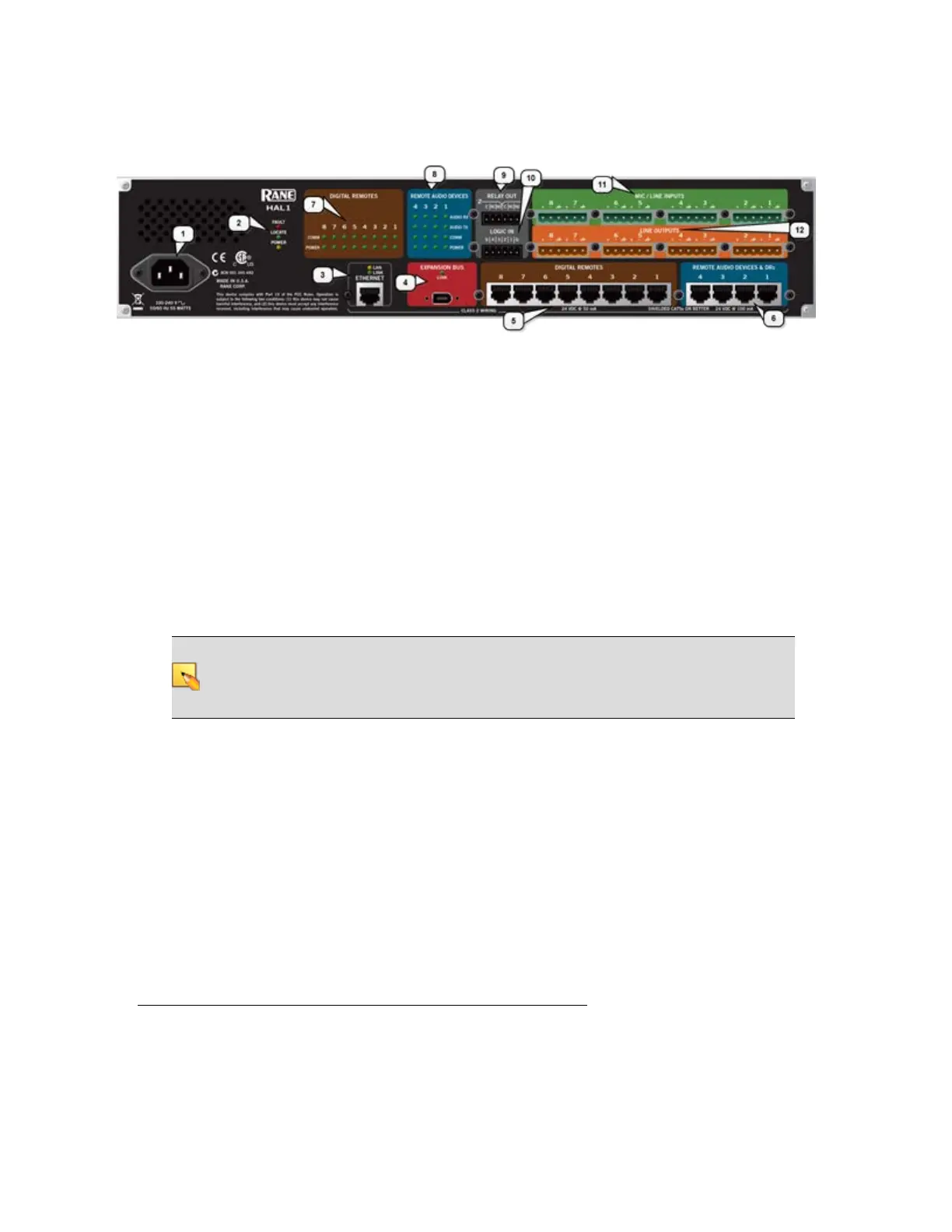
Rear Panel Description
1. The Power IEC jack connects to AC line voltage, 100-240 V, 50-60 Hz.
2. Fault, Locate, and Power LEDs
The Fault LED flashes red when something in the hardware goes awry. The first step in trou-
bleshooting the problem is to open the Halogen software and check the status of this HAL
device.
The Locate LED flashes green when you place this HAL device in Locate Mode (via the Hal-
ogen software). The purpose of this Locate functionality is for verification, when working in the
software, of the physical device you are configuring or viewing.
The Power LED lights when the HAL hardware is powered on.
3. Ethernet port and LAN and Link LEDs
Use this port to connect HAL to an Ethernet switch or directly to a computer.
NOTE: This Ethernet port contains auto-MDIX functionality, which means that you can
use either a standard Ethernet patch cable or a crossover cable to connect to a computer or
Ethernet switch. The auto-MDIX functionality takes care of coordinating the proper con-
nection between the devices.
The Ethernet LAN LED flashes when HAL detects any Ethernet packets on the network. The
Link LED indicates if the Ethernet network is connected. If HAL is connected to an Ethernet
network but the Link LED is off, there is likely a problem with the connection.
4. Expansion Bus LED and port
Use the Expansion Network port to connect an Expansion Network device (such as an EXP1)
to the HAL via Firewire
1
. To attach additional Expansion Network devices to your HAL Sys-
tem, use a Firewire cable to connect each new device to the previous device—in a daisy chain
style.
1
A form of connectivity similar to USB, meant to connect peripherals such as MP3 Players and digital
cameras to the computer. The HAL System uses FireWire to connect Expansion Units to the HAL
device. FireWire operates around 30 times faster than a USB 1.1 connection. FireWire is technically
known as IEEE-1394.
CHAPTER 2: Hardware Component Details
11