28
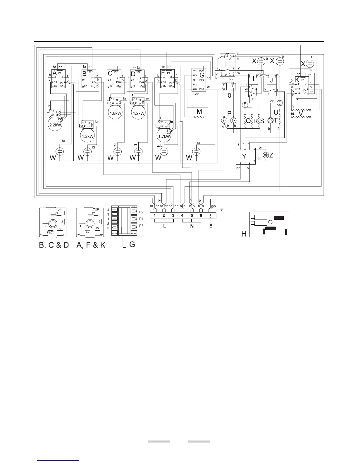
Circuit Diagram
Connection shown in circuit diagram is for single phase. Ratings are for 230V 50Hz
A Left hand end dual circuit hob energy regulator
B Left hand rear hob energy regulator
C Left hand front hob energy regulator
D Right hand rear hob energy regulator
E Earth terminal
F Right hand front hob energy regulator
G Right hand Warmer / hob controller
H Clock
I Left hand oven thermostat
J Right hand oven thermostat
K Grill energy regulator
L Line terminal
M Warmer Element
N Neutral terminal
O Oven light switches
P Oven light bulbs
Q Base element 1.0kW
R Top element 1.2kW
S Browning element 1.15kW
T Right hand oven fan
U Fan oven element 2.5kW
V Grill elements 1.15kW x2
W Hob indicator neons
X Facia indicator neons
Y Cooling fan controller
Z Cooling fan