9
6 Installation
Installation must be carried out by a qualified technician,
who takes responsibility both for installation and for put-
ting the unit into operation, as laid down in regulations.
6.1 Setting up
When setting up, follow the Technical ground-rules for
planning and operation of heating systems VDI
Guideline 2050. The height they specify for the base
60 to 70 mm should be observed, taking into account
that burners with downward-facing air intake manifold
require adequate clearance between air inlet and floor. It
may be necessary to use a higher base or a correspond-
ing recess in the floor. When installing several boilers
next to each other, there must be a minimum clearance
of 500 mm between boilers.
Noise insulation
To reduce the transmission of structure-born noise, spe-
cially made, tensioned, longitudinal insulation fasteners
are available for installation at the foot of the boiler.
We have measured the noise level without exhaust
gas noise insulation and this varies from 70 80 dBA,
according to make of burner, flue design, and load. This
value refers to a measuring point 1 m away from the roof
flue outlet.
If building conditions demand it, we recommend the in-
stallation of exhaust gas noise insulators.
A base for the boiler makes installing easier. Two sup-
port brackets are supplied for mounting under the foot of
the boiler.
If structure-noise absorbing elements (longitudinal insu-
lation fasteners) are used, special attention should be
paid to providing the boiler with an even surface to stand
on.
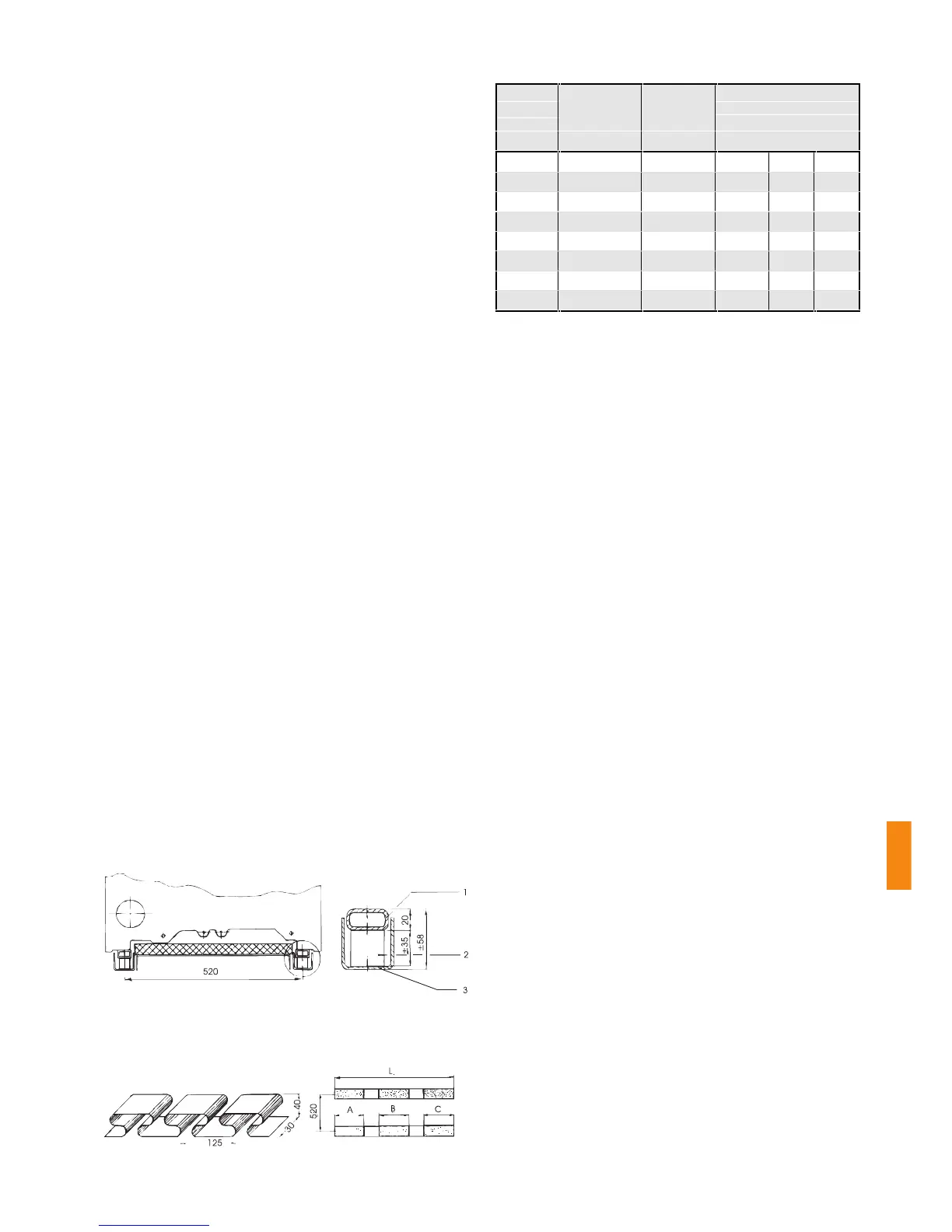
Longitudinal insulation fastener F 310
Stainless steel longitudinal insulation fastener as insulation element for
absorption of structure-born noise, consisting of damper in form of U-
bracket and RHS bracket for weight distribution (supplied as optional
extra).
6.2 Minimum clearances
To make installation and maintenance easier, the follow-
ing minimum clearances should be observed:
a) in front of boiler 1.500 mm
b) behind boiler 1.000 mm
c) on either side, at least 500 mm
6.3 Water supply-side connections
The heating advance and back-flow connections are in
the end section in the upper and lower boiler hub axis
extension (see Fig. 36, page 30). An opening is allowed
for in the back-flow connection elbow to permit boiler
filling and draining. Connect only those expansion tanks
that are permitted in the type of construction in question,
or which have been individually expert-tested. The safety
valve should be installed in the heating advance, in the
immediate vicinity of the boiler (valid for enclosed units).
Note on back-flow elevation
When installing in enclosed units, ensure that air is prop-
erly bled from the boiler and system. Sufficient circula-
tion must be maintained in the boiler under all operating
conditions.
A sufficient level is 1/3 of the water quantity correspond-
ing to the nominal boiler flow capacity.
To this end, the boiler must be pre-equipped with a cir-
culation pump of adequate capacity, installed between
the advance and back-flow (back-flow elevation).
Pump control is carried out via the rapidomatic
®
(acces-
sory).
No. of
sections
Weight Boiler length L Number and length of
longitudinal insulation
fasteners
kg mm A mm B mm C mm
9 1450 1350 2 x 250 2 x 375 2 x 250
10 1550 1500 2 x 375 2 x 375 2 x 250
11 1700 1650 2 x 375 2 x 375 2 x 375
12 1800 1800 2 x 375 2 x 375 2 x 375
13 1950 1950 2 x 375 2 x 500 2 x 375
14 2100 2100 2 x 500 2 x 500 2 x 375
15 2200 2250 2 x 500 2 x 500 2 x 375
16 2300 2400 2 x 500 2 x 500 2 x 375
boiler block
Detail A
Detail A
1 RHS profile tube 40 x 20 x 3
2 Type 3/1000 longitudinal
insulation fastener
3 U-rail 50 x 50 x 3
Dimensions of longitudinal insulation
fastener
For number and length of
longitudinal insulation
fasteners, see table
 Loading...