For a complete list of the contents of the development kit, please see the
SPECIFICATIONS tab.
Initial setup and checks
Inserting the Compute Module (CM) into the IO board
First insert the CM at a 45-degree angle, then gently press down on both top corners of
the CM (where the holes are) until it clicks into place.
Checking IO bank voltage jumpers
Please make sure that the two jumpers that power the GPIO bank 0 and 1 voltages are
present on J3, and set to the voltage you wish to use. Do not power up the board if
these jumpers are not attached (and hence the GPIO bank(s) are unpowered), as
this may damage the Module.
Powering up
Make sure the CM is inserted correctly into the socket (J1). Make sure the GPIO banks
are powered (make sure J3 has jumpers present and set correctly). Attach a micro USB
power supply to J2 (POWER IN) to power up the board.
Note that at this point the red power LED and green ACT LED should light up. Nothing
further should happen (because the Compute Module Flash (eMMC) is blank).
Loading an OS image and further documentation
The next step is to write an operating system image to the onboard eMMC Flash. Once
this is done, the board should boot into the OS of your choice when you power up.
Further documentation, including a step by step guide to flashing the eMMC, is
available.
SPECIFICATIONS
The Compute Module Development Kit is made for developing industrial applications
with CM3+, CM3+/Lite, CM3, CM3 Lite, and CM1.
The Development Kit contains the critical hardware that allows you to design the
Compute Module into a custom system, and gives you the freedom to add extra
components and place parts exactly where your product needs them.
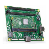
The kit includes the Compute Module IO (CMIO) board, which is a simple, open-source
breakout board into which you can plug a Compute Module. The board hosts 120 GPIO
pins, an HDMI port, a USB port, two camera ports, and two display ports.
 Loading...