Page 4
RUN LED FLASHES GREEN POWER SUPPLY IS OK
BAT LED IS ALWAYS ON BATTERY IS OK
SIM LED IS GREEN OR AMBER DEVICE IS CONNECTED TO THE NETWORK
COVERAGE LED IS GREEN OR AMBER GOOD COVERAGE
SLIC LED IS GREEN DEVICE IS IN STANDBY
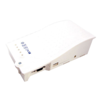
J9 / J1A - PHONE LINE (SLIC)
6. Wait for the LED lights to turn on. Check the SIM LED to make sure it is green or amber. If it is ashing red,
check that the SIM card has been inserted correctly.
7. A signal strength test is recommended. Check the signal strength by using the built-in network signal strength
scanner. To use the scanner function, turn on SW1 dipswitch 1 to ON (check that dipswitch 4 is also ON). See
“Signal Strength Test” section on page 9 for more information.
8. Plug power cord into 120vac power source or turn on 120vac power source.
9. Place the lid back on the top of the Cellular Gateway and fasten the lid with the screw.
10. The RUN LED should change color from ashing amber to ashing green when the main power connection is
made. If you see any other color, please consult the LED indication list.
5. Connect the phone(s). The Cellular Gateway provides an RJ11 jack or hardwired screw terminals for
connecting devices.
RJ11 Jack:
a. Take a male RJ11 phone line cord or plug it into the J1A jack on the Cellular Gateway.
b. Plug the other end of the line cord into desired device.
Hardwired Connection:
a. Gently remove provided 2 pin connector from J9 on the Cellular Gateway.
b. Screw the 2 wire connection from the desired device into the 2 pin connector. Pin 1 is tip (neutral) and pin 2
is ring (positive).
c. Plug the 2 pin connector back into J9.
J1A
J9
 Loading...