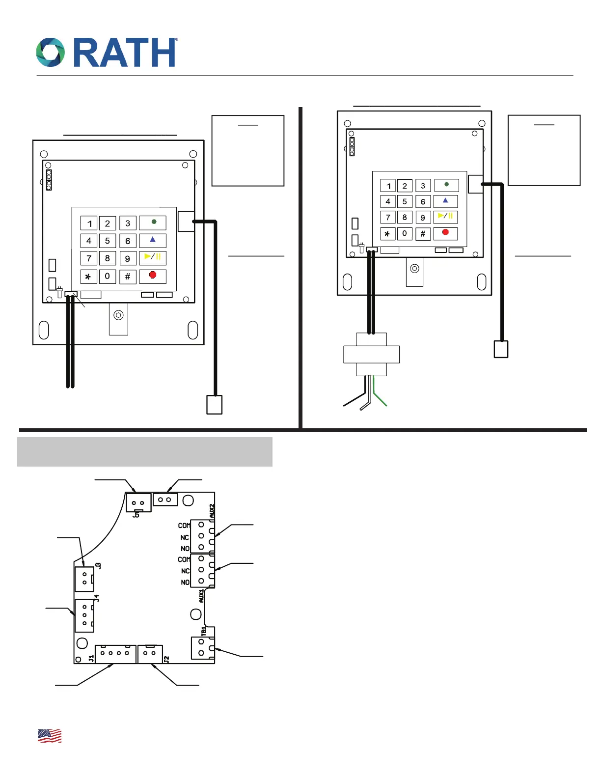
Wiring Diagrams: 24vac/dc Models
Enter
Record
Play/Pause
Stop
Bat
1
1
J
R
11JR
mralAyaleR
hctiwSDEL
MIC Speaker
+ -
24v
ac/dc
Direct 24vac/dc Powered
120vac to 24vac/dc Powered
Enter
Record
Play/Pause
Stop
RP7300144-24/5VA
Black
Hot
Green
Ground
White
Neutral
120vac
Bat
mr
a
lAyaleR
hct
i
w
S
DE
L
MIC Speaker
+ -
1
1
J
R
11JR
To Speaker
Relay 1
Relay 2
To H1 on SP VI
To Speaker connection
on SP VI Circuit Board
To Audio output
of Annunciator
To LED on SPVI
24v LED 24vdc Power for LED
-+
-+
-+
1. Connect your annunciator’s audio output to the TB1 connection
on this board.
2. When utilizing this board to drive a 24v LED, you must apply
power to the wire leads at the TB2 connection. You may tap into
a direct 24vdc supply that has battery backup. Connect the wire
leads at the J5 connection to your LED.
3. If you are not utilizing this board to drive a 24v LED, you need
to disconnect the LED harness from the SmartPhone board,
disconnect the LED harness from this board, connect it to the
SmartPhone board, and then wire to your standard LED.
4. If you want to activate Relay 2 in unison with Alarm Relay on
SmartPhone board, follow these programming steps (default
activates upon call out):
a. Press ENTER
b. Press 3, 0, ENTER, 4
c. Press STOP for 3 seconds
*
*
24v
To 24vac/dc Power Supply
To Phone Line:
Requires a twisted
shielded pair.
When used with
SmartRescue,
requires two
twisted shielded
pairs.
To Phone Line:
Requires a twisted
shielded pair.
When used with
SmartRescue,
requires two
twisted shielded
pairs.
Note:
If Elevator
Communications
Failure is
required, connect
to our
Alarm Relay *
Note:
If Elevator
Communications
Failure is
required, connect
to our
Alarm Relay *
RP8200910
Ver. 8
09/19
Annunciator Interface,
Auxiliary Relay & 24v LED Board
TB2
Troubleshooting & Diagrams
SmartPhone VI
N56W24720 N. Corporate Circle • Sussex, WI 53089
800-451-1460 • www.rathcommunications.com
MADE IN THE USA
3 YEAR WARRANTY
 Loading...