UV/EH V06 08/2015 - 10 -
- Disconnect unit from mains, on which UV/EH shall
be installed
- Check door of the unit for correct adjustment
- Replace rear screw of the top door holding
plate by stud (item7) and washer. pic. 6
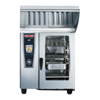
- Carefully place the UV/EH onto the unit. pic. 7
- Fasten UV/EH with screw and washer (item8)
to previous installed stud. pic. 8
- Remove the left side panel of the unit.
4. Installation of the bus cable
- At the rear side of the UV/EH the connection box
with the control pcb is located.(pic. C/D/E/F).
- A bus cable is connected to the control pcb and
guided through the cable gland of the connection
box. An additional cable gland is installed
to the bus cable. pic. 10
- There are knock outs in the bottom of the electric
compartment. Break one of these out. Run the bus
cable of the UV/EH through this knock
out and fix the cable gland to it. pic. 11
- Additionally fix shielding plate (item 11) to
cable gland and connect it to the shield of the
bus cable (cut out insulation of the bus cable)
pic 10
- Connect the bus cable to the unit:
on electric units at a free connector of the
motor control pic. 12
on gas appliances at a free connector of an
ignition box pic. 13
- The cable can be axed to the back of the appli-
ance with the self-adhesive cable clips
(pic.1 item 3) supplied. pic. 14
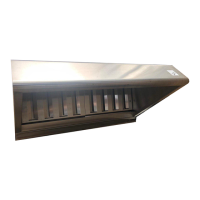
5. Drain for condensation water.
On the rear side of the UV/EH a drain
connection for condensation water is installed
- Fit the silicone hose (pic 1 item 4) with the hose
clamp (pic 1 item 5) to the elbow. pic. 15
- Put the drain pipe (pic 1 item 6) to the drain
of the unit. pic. 16
- Shorten the silicone (pic 1 item 4) hose to the
desired length and connect it to the drain
pipe (pic 1 item 6). pic. 16
6. Electrical connection of the UV/EH
Danger
Observe local regulations and standards
during installation
Warning
Observe colour coding of the wires. Wrong connec-
tion can cause electric shock
Attention:
Wrong connection can cause damages (e. g. fan
motor)
Colour coding of wires:
yellow/green = earth
blue = neutral
black = Phase
- The UV/EH must be connected to a standard mains
in accordance with the local regulations.
- Before pulling the plug or reconnecting to the power
supply, make sure that the SelfCooking Center or
the Combi Master is switched o to avoid that the
UV/EH starts to run.
- A permanent connection shall be provided for the
UV/EH. On-site installation:
provide accessible all-pole disconnection device
with a minimum of a 3 mm contact gap. If the UV/
EH shall be connected with a plug make sure that it
is accessible
- The UV/EH must be protected on site with a maxi-
mum fuse of 16 A. The UV/EH is fitted with a cable
approx. 2 m in length without plug.
- If the power cord shall be changed, the quality of
the cord must be at least
H05 RN-F 3x1,5 mm
2
In case the power cable must be changed use a
cable that matches your local standards.
The exchange of the power cable may only be car-
ried out by the manufacturer, his service agents or
similar qualified personal
Installation instruction
 Loading...