- 11 - UV/EH V06 08/2015
Equipotential bonding
Also on the rear side of the UV/EH there is a
stud for the equipotential bonding. Integrate
the UV/EH with a suitable cable into the
equipotential bonding system.
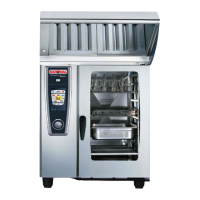
Observe on Combi-Duo:
- Connect the vent pipe of the Combi-Duo to the con-
nection piece of the UV/EH using hose (item 9) and
hose clamp (item 10) of the UV/EH kit. pic. 9
- Installation of the bus cable:
There are two bus cables connected to the control
pcb. Use the longer cable for the bottom unit and
the shorter for top unit. Connect the cable as
described under point 4.
Observe on gas units
- Connect the bus cable to a free connector of the
ignition box (see point 4)
- UV/EH gas is shipped with 3 extension pic. 19
pipes for exhaust system. For unit size 6x1/1 GN
one pipe with outer diameter 42 mm and one pipe
with outer diameter 54 mm is required. Unit size
10x1/1 GN requires two pipes with outer diameter
54 mm. Attach the required pipes to the corre-
sponding exhaust pipe of the unit..
In case an additional draft diverter is ordered with
UV/EH these pipes are not required. The draft
diverter is shipped with extra longer pipes (see
installation instruction of draft diverter)
- The use of this EH or Ultravent does not
replace the flue gas evacuation via extraction hood,
ventilated ceiling or chimney.
- If the waste gas of the combi steamer is
removed by means of a chimney, then a draft
diverter must be fitted to the exhaust opening of the
UltraVent
®
.
- The draft diverter is not included in the scope of
supply of the unit, but can be ordered with the fol-
lowing part number:
6x1/1 GN # 70.00.759
10x1/1 GN # 70.00.793
7. Technical intervention
Before any intervention or maintenance work,
disconnect the appliance from the power supply.
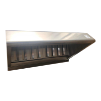
7.1 Fan motor.
Fan motor is accessible after removing the
fat filter. pic. 17
7.2 Changing halogen bulb. pic. 18
After loosen the holding frame, the halogen bulb
can be changed.
8. Wiring diagram
see pictures C/D/E/F
9. Service parts
Description Art. No.
Control pcb 42.00.050
Bus cable 40.04.148
Bus cable (4,3m Duo) 40.04.146
Fuse 5 x 20 2,5A 3019.0117
Halogen bulb 3024.0201
Inner gasket for interior light 40.00.094
Glass pane for interior light 40.00.095
Gasket frame for interior light 40.00.092
Fat filter left 60.72.440
Fat filter right with lock 60.72.441
Adapter plate left hinged door
(Pos. 1) 61/101 60.72.891
Adapter plate right hinged door
(Pos. 1) 61/101 60.72.936
Adapter plate right hinged door
(Pos. 1) 62/102 60.72.937
Gasket adapter (Pos. 2) 61/101 60.72.431
Gasket adapter (Pos. 2) 62 60.72.433
Gasket adapter (Pos. 2) 102 60.72.435
Gasket adapter (Pos. 2) 201 60.72.445
Stud (Pos. 7) 60.72.892
Drain pipe (Pos. 6) 60.70.735
Silicone hose 2110.1008
Contactor k1/K2 40.03.687
Capacitor 3,5 uF 40.04.151
Capacitor 10 uF 40.04.152
Capacitor 14 uF 40.04.229
Capacitor 40 uF 40.04.230
Voltage related parts for input voltage:
Extractor fan 200-240V (M1) 60.72.439
Extractor fan 100-127V (M1) 60.72.701
Installation instruction
 Loading...