installation
Step 12.
Connect the power source
and verily the pilot lamp, located by the power switch on the
Central Control Assembly, remains off.
Step 13.
Place the power switch to the ON position (up) and verily the
pilot lamp lights.
Note:
Other lamps may also be seen to illuminate within the TC4001.
Step 14.
Place the
power switch in
the
OFF
position and verify all illuminated
Iamps
go out.
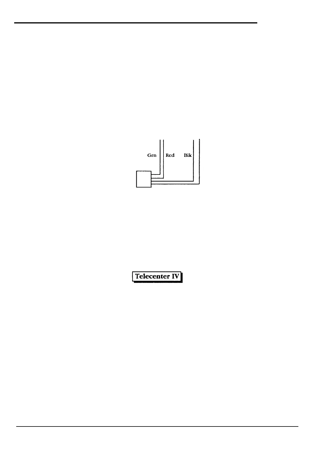
Step 15.
Install a modular connector at a convenient place in the cabinet and connect the
“T”
and
“R”
twisted pair to physical number 5 of
LLM
0 (TC4150) located in the
TC4001
and the Black
and
Yellow
twisted
pair
to the
LCD 1
pins on the
MI0
(VC7166),
as
shown in the following
figure.
LLM Physical
Number
5
MI0 LCD 1
TR
+-
Ye1
Modular
Connector
NOTE:
These connections can be
paralled
for connecting another phone, if necessary.
Step 16.
Step 17.
Connect
a display phone
to the modular connector installed in Step 15.
Place the power switch to the ON position and verily the display shows the message:
Step 18.
Lift
the receiver
of the display phone and verify dial tone is received, then place the phone
back on hook.
Step 19.
If Central Office or PBX trunks are installed or if there are any lines which leave the building,
ensure lightning protection is installed on each (see drawing KM0714).
©
1989
R&and-Borg Corporation (Orig.
10/88;
Rev. l/89)
Page 5 of 20
 Loading...