Installation
Configure Line-Link Modules
Summary:
Ensure the
DIP
switch setting on each TC4150 Line-Link Module
(LLM)
is in accordance with
system requirements.
Equipment required:
Small flashlight, six-inch long, small shank
(#l),
flat-bladed
screwdriver, pliers.
Step 1.
Refer to the
Physical Number Layout
Planning
Worksheet
and determine which LLM’s are
required to support the physical numbers noted on the
System Planning Worksheet
for
Central Equipment Phone LLM’s.
Step
2.
Go
to the front of the system cabinet and locate the LLM’s.
LLM
0 is in the Central Control
Assembly (TC4001) and all other LLM’s are immediately below in the expansion chassis.
Step 3.
Using the flashlight, peer through the inspection port on the left side of each
LLM
and locate
the DIP switch behind the ribbon cable connector. Compare the factory set
DIP
switch
settings with the
LLM
DIP Switch Settings Table
below, keeping the following in mind:
The DIP switch setting provides the system address for the range of physical numbers
supported by a particular LLM.
The LLM number (O-31) is determined by the physical numbers required, not the
number of LLM’s in the system. Refer to the column marked
PHYS.
in the table below
for the range of physical number associated with each LLM.
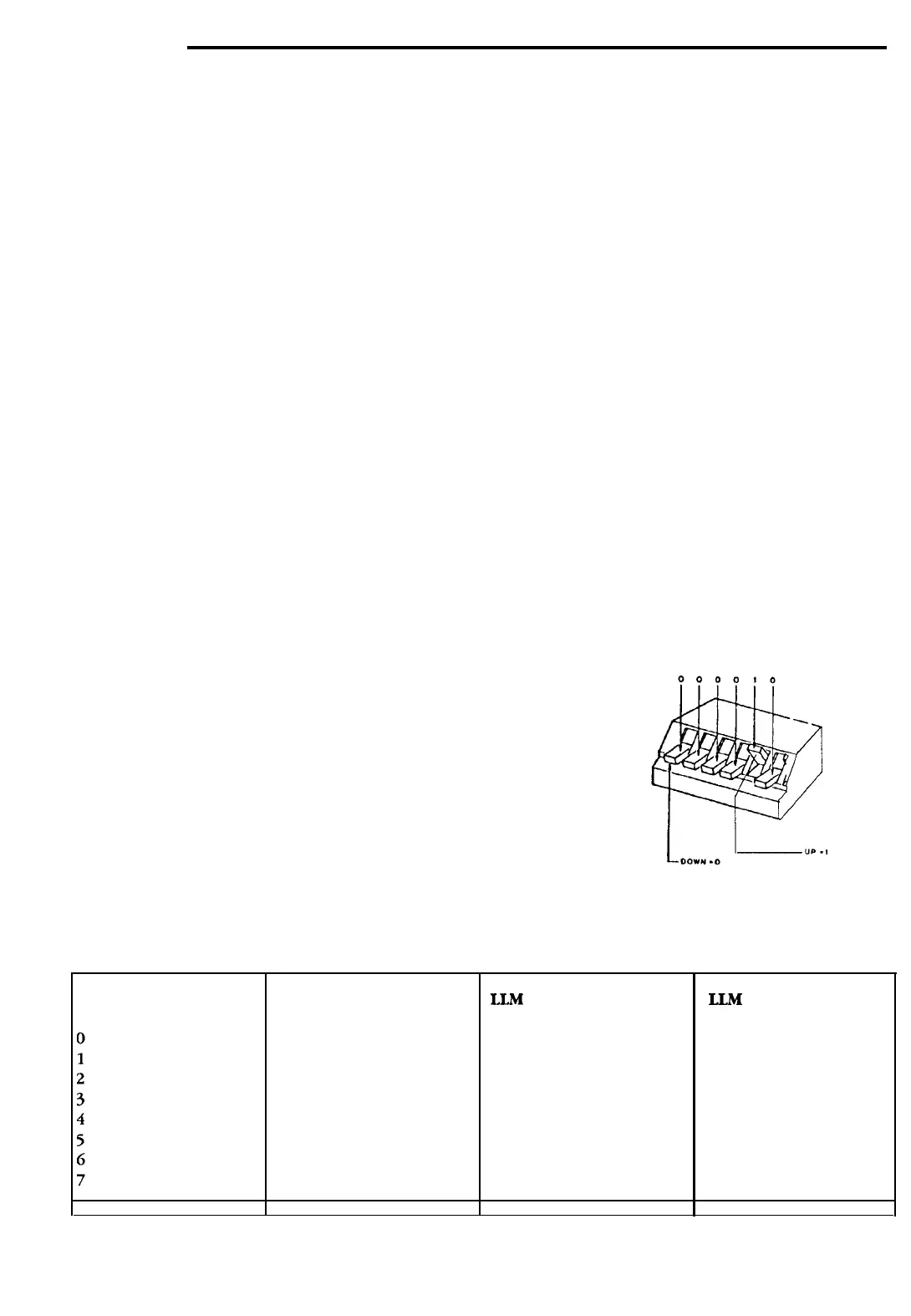
0
means
the switch is down.
1 means
the switch is up.
Step 4. If setting must be changed, use this figure as a guide to
toggle the switches as necessary. This can be done in one of
two ways: Insert the screwdriver through the inspection
port; or, go to the rear of the cabinet and remove the LLM
after straightening the retaining tabs which hold it in place.
Step 5.
On the chassis near the ID strip, mark the LLM with the first
and last physical numbers it supports and remove any con-
flicting factory markings.
LLM DIP Switch Settings Table
LLM
DIP
PHYS.
LLM
DIP
PHYS.
000000
00000
1
000010
000011
000100
000101
000110
000111
o-15
8
001000 128-143
16
010000
256-271
24 011000
384-399
16-31
9
001001 144-159
17
010001
272-287
25
011001 400-415
32-47
10
001010 160-175
18
010010 288-303
26
011010 416-431
48-63
11
001011
176-191
19
010011
304-3 19
27
011011 432-447
64-79
12
001100 192-207 20 010100
320-335
28
011100 448-463
80-95
13
001101
208-223
21
010101
336-35 1
29
011101 464-479
96-111
14
001110 224-239
22
010110
352-367
30
011110 480-495
112-127
15
001111 240-255
23
010111
368-383
31
011111 496-511
DIP PHYS.
DIP PHYS.
Page
6
of
20
©
1989
Rauland-Borg
Corporation (Orig.
10/88;
Rev. l/89)
 Loading...