Installation
Configure Speaker (and Single Link Staff Phone) Control Boards
Step 2.
Step
3.
Step 4.
Summary Ensure the DIP switch on each TC4110 (SC25) and TC4120
(SCC25)
Speaker Control
Board is correctly set in accordance with system requirements. Throughout this procedure,
both types of Speaker Control Boards will be referred to as
SC’s.
Step 1. Refer to the
Physical Number Layout Planning Worksheet
and determine which SC’s are
required to support the physical numbers noted on the
System Planning Worksheet
for
Central Equipment
Phones and Speakers.
If Single Link Staff Phones are used, determine the installation configuration before proceed-
ing. Single Link Staff Stations always include a Speaker but they must not be wired to the
same SC board. Speaker SC’s may or may not be connected to switch panels; therefore, there
are two possible SC configurations when Single Link Staff Phones are used:
One SCC25 for groups of up to 25 Speakers (no switch panels) and,
One SCC25 for groups of up to 25 Single Link
Staff Phones.
One SC25
for groups
of
up to 25 Speakers (connected to switch panels) and,
One SCC25 for groups of up to 25 Single Link
Staff
Phones.
At the back of the system cabinet, locate the SC’s above the Central Control Assembly.
Speaker and Phone SC’s may be identified as follows:
Speaker SC
Sl
and
S2
terminals are bussed to the
MI0
via a shielded cable.
Phone SC
Sl
and S2 terminals are bussed to one
LLM
line via a twisted pair.
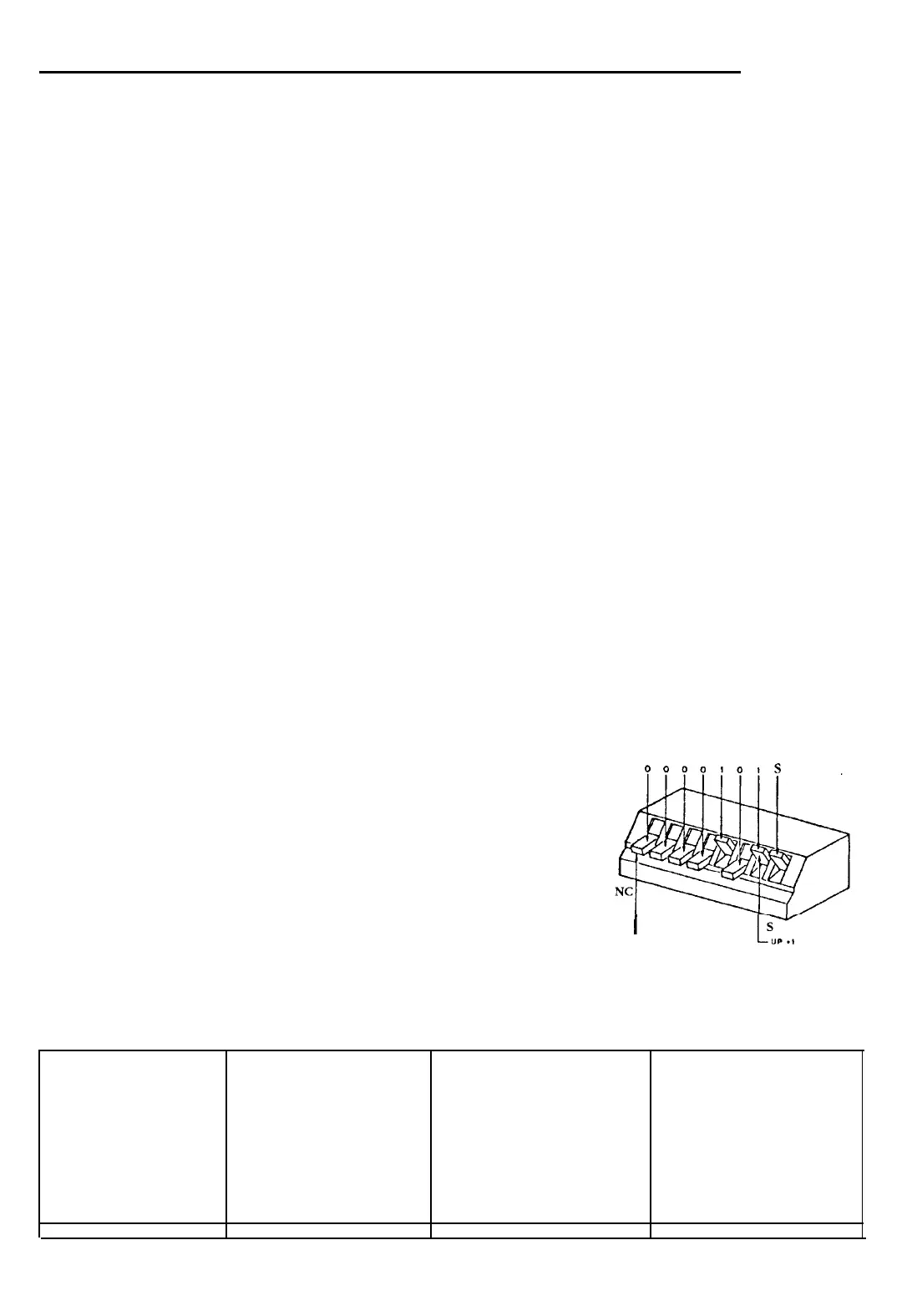
Locate the DIP switch next to the ribbon cable connector on the left side of each SC and
compare the switch settings with the table below, keeping the following in mind:
Step 5.
The switch setting provides the system address for the
entire range of physical numbers supported by a particu-
lar board. The SC number (O-19) is determined by the
physical numbers required, not the number of SC’s in the
system. (SC 48 is not normally used.)
If Single Link Staff Phones are used, Control Boards are
mounted in pairs having the same DIP switch setting
except for the rightmost lever (S). This lever must be
Down
for a
Phone SC
and
Up
for a
Speaker SC.
If DIP switch settings must be changed mark the new
setting near the ID strip on each module and remove any
conflicting factory markings.
SC
DIP Switch Settings Table
SC DIP
PHYS..
SC DIP
PHYS.
48
0110000(S)
o-15
4
0000100(S)
116-140
0
0000000(S)
16-40
5
0000101(S)
141-165
1
0000001(S)
41-65
6
0000110(S)
166-190
2
0000010(S)
66-90
7
0000111(S)
191-215
3
0000011(S)
91-115
8 0001000(S)
216-240
0000,0,s
I
L
DOWN
-0
SC
DIP
PHYS.
9
OOOlOOl(S) 241-265
10
0001010(S)
266-290
11
0001011(S)
291-315
12
0001100(S)
316-340
13
0001101(S)
341-365
SC
DIP
PHYS.
14
0001110(S)
366-390
15
0001111(S)
391-415
16
0010000(S)
416-440
17
0010001(S)
441-465
18
OOlOOlO(S)
466-490
19
0010011(S)
491-511
©
1989 Rauland-Borg Corporation (Orig. 10/88; Rev.
l/89)
Page 7 of 20
 Loading...