KI-1698B
TC4221 Digital Display
Installation
RAUUNDBORG
CORPORATION l 3450 West Oakton Street, Skokie, Illinois 60076-2951 l (847) 679-0900
General Information
Description Parts Enclosed
This unit comes assembled on a
metal
baseplate. It con-
verts a standard push-button phone to a display phone that
can be used with Telecenter V, Telecenter IV, Telecenter
TCS, Telecenter System 21, or TCll00 systems. It has a
16-digit LCD readout and a “beeper” to annunciate call-ins.
The TC4221 can be used as a direct replacement for a TC4220,
but it offers a number of new features as well, notably its
capability of being individually addressed in a Telecenter V
and Telecenter System 21 system.
The following parts should come with the display:
4 1” x 2 1/2” double-sided foam strip, for fastening the
display to the telephone.
4 Nine-inch, six-conductor modular phone cord.
Number of Displays
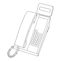
The display matches the Rauland TC4204 Administrative
Telephone. It can be used with many other DTMF (dual-fre-
quency, multi-tone) desk phones, the only limitation being
aesthetics. Figure 1 shows a typical placement.
Telecenter V and Telecenter System 21 systems have a
single display driver that can support up to 2,000 feet of
cabling and 16 displays. Each display may be assigned its own
address with its DIP switch (see “Setting the DIP Switch,” the
final section of this manual).
Telecenter 1100, Telecenter IV, and Telecenter TCS sys-
tems can support up to 1,000 feet of cabling and three displays
per display driver. Telecenter 1100 systems have one display
driver, Telecenter IV systems have two display drivers, and
Telecenter TCS systems have six display drivers.
Figure 1. Typical Placement of Display
Related Manuals
See the appropriate system manuals for details on wiring
and programming:
Telecenter V
The main wiring diagram (KM1035) includes the wiring
for display phones. It is part of the Telecenter V drawings
manual, included in KI-1687.
Telecenter IV
The wiring diagram for display telephones (KM0684) is in
the Drawings and Glossary manual (KI-1587), which is part of
the main manuals (KI-1435). For programming information,
see KI-1584, also part of the main manuals.
Telecenter TCS
The wiring diagram for display telephones (KM0837) is in
Diagnostics, Troubleshooting, and Drawings (KI-1550), which
91993
RAULAND-BORG CORPORATION.
Printed in U.S.A. Page 1 of 5
Orig. 2/92. Rev. 8/92, 9/93. 169802