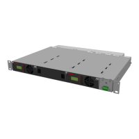
The PowerPlus RDIDC-100-3R-1U-X is a rack-mounted system designed to boost the voltage of a telecom power supply, primarily to reduce current on power cables and maintain a constant output voltage to remote radio heads (RRHs) during battery discharge. This system is particularly beneficial in split Radio Base Station (RBS) architectures where RRHs are connected to a Base Band Unit (BBU) via cabling, leading to voltage drops over long DC power cables. By boosting the voltage, the PowerPlus system reduces power losses, improves overall system efficiency, and extends the operational time of radios during power outages.
Function Description:
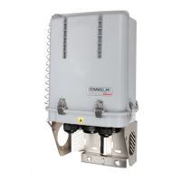
The PowerPlus RDIDC-100-3R-1U-X system operates by taking a -48VDC input from a DC power plant or battery bank and boosting it to a user-configurable output voltage, typically up to -58VDC. This boosted voltage compensates for voltage drops that occur over long DC power cables, ensuring that RRHs receive a stable and adequate power supply. The system is composed of a mounting rack and up to three pluggable modules. The output of each module is designed to connect to a Raycap Power Distribution Unit (PDU), specifically the RDIDC-9052-PDU-48.
The system incorporates a primary-secondary module management scheme. There is always one Primary module that controls the overall system operation. In the event of a Primary module failure, a Secondary module automatically takes over as the new Primary, ensuring continuous operation. All modules display the input and output voltage, with the Primary module identifiable by a "P" character at the end of the input voltage value on its display.
Important Technical Specifications:
- Input Voltage Range: -58Vdc to -40Vdc (+/- 0%).
- Output Voltage Range: User-configurable from -54V to -58V, adjustable in 1V increments.
- Rated Output Power (kW): Input Voltage (Vdc) * 275 (A).
- Maximum Rated Current (per module): 110A.
- Operating Ambient Temperature: Compatible with environments up to 55°C.
- Rack Space: 1U vertical space required for installation.
- Remote Contact Alarm Rating: Maximum rated current of 2A.
- Cable Length Compensation: Designed to compensate for voltage drop over DC power cables, especially for lengths exceeding 240 feet.
Usage Features:
- Voltage Boosting: Actively boosts the voltage from the PSU output to overcome voltage drops on DC power cables, ensuring stable power to RRHs.
- Configurable Output Voltage: Users can set the desired output voltage between -54V and -58V in 1V increments during installation or through the live settings menu.
- Single and Dual Module Configurations: The manual details configurations for one or two modules, recommending appropriate breaker sizes (150A for single, 300A for dual) and lug types for input, output, and ground connections.
- Rack Mountable: Designed for installation in standard 19" or 23" racks, with a rack extension kit provided for 23" racks.
- Front Panel Display: Each module features a display showing input and output voltage, as well as status messages and alarms.
- User Interface: Simple navigation using 'UP', 'DOWN', and 'ENTER' buttons for module settings and alarm management.
- Remote Alarm Contacts: Provides remote contacts that change state (from normally open to closed, or vice versa) when an abnormal condition is detected, allowing for remote monitoring of system health.
- LED Indicators: Front panel LEDs change from GREEN to RED to indicate alarm conditions.
Maintenance Features:
- Module Replacement (Hot and Cold):
- Cold Module Replacement: Modules can be replaced when the system is powered OFF. The system will exchange stored settings upon boot-up, and if discrepancies are found, it will enter "SETTINGS" mode, prompting for new settings.
- Hot Module Replacement: Modules can be replaced while the system is powered ON and operational. The system automatically transfers configured output voltage settings to the new module, and operation continues uninterrupted. This is the recommended method to avoid re-entering initial settings.
- Automatic Module Configuration: When a new module is installed (especially during hot replacement), the system automatically configures it as a Secondary module and transfers the necessary output voltage settings.
- Alarm Management:
- Module Failure Alarm: Raised when a Secondary module fails, indicated by an LED change to RED, remote contact change, and "MODULE FAILURE" message. Cleared by pressing 'ENTER' on the Primary module for 3+ seconds after replacement.
- Primary Module Failure Alarm: If the Primary module fails, a Secondary module takes over and becomes the new Primary, raising a "PRIMARY FAILURE" alarm. Cleared by pressing 'ENTER' on the new Primary module for 3+ seconds after replacement.
- Overcurrent Alarm: If a module's current exceeds 110A for more than 3 seconds, it enters bypass mode and displays "HIGH CURRENT." If a Secondary module overcurrents, the Primary raises a "MODULE FAILURE" alarm. If the Primary overcurrents, a Secondary takes over and raises a "PRIMARY FAILURE" alarm.
- Low/High Input Voltage Alarms: "IN VLT LOW" or "IN VLT HIGH" messages are displayed if the input voltage falls below the minimum or exceeds the maximum for more than 3 seconds. Alarms clear automatically when voltage returns to normal.
- Extra Low Input Voltage Alarm: If input voltage drops below -38V for more than 200msec, all modules go to bypass and display "EXTRA LOW Vin."
- Temperature Alarm: "HIGH TEMP" is displayed if a module's internal temperature exceeds its maximum rated limit for more than 3 seconds. If a Secondary module overheats, the Primary raises a "MODULE FAILURE" alarm. If the Primary overheats, a Secondary takes over and raises a "MODULE FAILURE" alarm.
- System Low Temperature Alarm: "LOW TEMP" is displayed if the system temperature falls below -35°C for more than 250 seconds. Modules go to bypass until temperature returns to normal.
- DC/DC Converter Failure Alarms: "DC/DC ALERT" for short circuits at the output (20msec+) and "DC/DC COM FAIL" for internal converter communication failures. These halt output to prevent device damage.
- Settings Menus:
- Initial Settings Menu: Appears during system boot if conflicting settings are detected or in an empty system, allowing for initial configuration of output voltage.
- Live Settings Menu: Accessible by simultaneously pressing 'UP' and 'DOWN' buttons on the Primary module for 3+ seconds during normal operation, allowing for configuration changes without interrupting service.
- Touch Guard: Includes a touch guard set for safety, which needs to be released via push pins for maintenance.
- Terminal Connections: All PowerPlus terminal connections are 1/4-20 studs, with a recommended torque of 65 in-lbs.