Do you have a question about the Rayleigh Instruments RI-F300 and is the answer not in the manual?
Details display, input, installation category, frequency, and environmental parameters.
Specifies RS485 communication and pulse output characteristics.
Essential steps for valid MID installation: CT ratio setting and sealing.
Parameters lock after 15 minutes in programming mode without return to supplier.
Table showing energy reading resolution based on PT/CT ratios and an example.
Follow safety notifications, symbols, and ensure correct usage; avoid hazards.
Only install by competent personnel due to electric shock risk.
Isolate power, verify connections, use specified cables, and comply with local standards.
Procedure to change CT primary input orientation for load monitoring.
Procedure to verify the CT rotation setting on the meter display.
Description of the 6 dedicated keys for parameter viewing.
Meter returns to default page if no key is pressed for 60 sec.
Shows line-neutral/line-to-line voltages and their harmonics.
Displays current parameters, max demand, and harmonics.
Displays voltage, current, power factor, and frequency for each phase.
Displays power factor for each phase and average PF.
Displays active, reactive, apparent power, and demand values.
Displays various energy parameters (import, export, net) by phase and total.
Details available screens for 1-phase 2-wire systems and default behavior.
Press PF key for 10 sec to display CRC, HW/SW versions, and serial number.
Use 'E' button for 3 seconds to switch between auto and manual page scroll.
EC Type Examination Certificate and tested standards for MID compliance.
Use specific keys for 3 sec to enter/exit the configuration menu.
Use arrow keys for cursor movement and value adjustment.
Use the 'Enter' key to save settings and move to the next page.
Setting password, network selection, CT/PT primary and secondary values.
Configuring Slave ID, Baud Rate, Parity, and Stop Bit.
Configuring backlight, demand intervals, and page sequence.
Setting pulse resolution, duration, and meter reset options.
Shows dimensions and required panel cutout for installation.
Steps for preparing the panel and securing the meter.
Identifies terminals for CT input, RS485, Pulse Output, and Voltage Input/Output.
Only compatible with specified Rayleigh Instruments CTs.
Meter requires Neutral; Voltage output supports daisy-chaining.
Addresses for Password, Slave ID, Baud Rate, Parity, and Stop Bit.
Addresses for Backlight, Auto Mode Pages, and Page Address Sequences.
Addresses for Demand Interval settings and Reset functions.
Formula to calculate addresses for individual harmonic measurements.
Example calculation for finding the address of Voltage V31 14th Harmonic.
Addresses for voltage, current, and frequency readings.
Addresses for active, apparent, reactive power, demand, and energy values.
Addresses for Total Harmonic Distortion, Phase Sequence, and rollover counters.
Describes the semiconductor pulse output and its interface options.
Diagram showing connections for RS485 communication and daisy-chaining.
Recommends terminating resistor and shows example meter displays.
Contact details and website for Rayleigh Instruments Ltd.
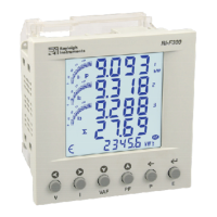
The Rayleigh Instruments RI-F300 is a three-phase energy meter designed for monitoring electrical parameters in various environments. It features a liquid crystal display with a backlight, showing 4 lines of 4 digits for electrical parameters and a 5th line of 8 digits for energy, accompanied by a bar graph for current indication as a percentage of the CT rating. The device is housed in a 96mm x 96mm enclosure and is suitable for panel mounting.
The RI-F300 measures and displays a wide range of electrical parameters, including line-to-neutral and line-to-line voltages, phase currents, neutral current, power factor, active power, reactive power, apparent power, frequency, and harmonics. It also tracks energy consumption (import and export active, reactive, and apparent energy) and run hours. The meter supports demand interval measurements for active, reactive, and apparent power, with configurable demand interval methods (sliding or fixed) and durations.
The device offers extensive programming capabilities through a dedicated menu, allowing users to configure network selection (3P4W, 1P2W-P1), CT and PT ratios, slave ID for communication, baud rate, parity, stop bits, backlight duration, page sequences for display, pulse resolution and duration, and to perform factory defaults or reset energy and maximum demand parameters.
The RI-F300 offers a user-friendly interface with 6 dedicated keys for navigation and parameter viewing. The display can be set to automatic or manual scrolling for different pages of parameters. The meter provides detailed online pages for viewing various measurements, including voltage, current, power factor, and energy readings for each phase and total. It also displays maximum and minimum demand values for power.
For MID approval, specific installation steps must be followed: the CT ratio must be set before service, and the RJ45 connection between the meter and the current transformer must be sealed. A configuration lock feature restricts parameter adjustments after 15 minutes in programming mode, preventing unauthorized changes.
The device supports Modbus RTU communication over RS485, allowing integration into larger monitoring systems. It can be daisy-chained with up to 31 additional meters for voltage output.
The manual emphasizes safety precautions, stating that only competent personnel should install the device. Users are advised to isolate the power supply before any work, confirm absence of supply, and ensure correct wiring. The equipment should not be used if mechanically damaged or supplied with incorrect voltage. Repairs, maintenance, or adjustments by the user are not permitted.
The device is designed for installation in Mechanical Environment 'M1' (low shock and vibration) and Electromagnetic Environment 'E2'. Wiring guidelines specify cable cross-sections (0.5mm² to 2.5mm²), copper cable usage, and adherence to local standards.
The meter includes a feature to reset maximum demand and energy parameters, protected by a password. It also allows for resetting the run hour. The device identification, including CRC, hardware/software version, and serial number, can be accessed through a specific key sequence for diagnostic purposes.
| Brand | Rayleigh Instruments |
|---|---|
| Model | RI-F300 |
| Category | Measuring Instruments |
| Language | English |