Do you have a question about the Raymarine RA1072HD and is the answer not in the manual?
Provides critical safety warnings for installation and operation, including electrical and navigational safety.
Details RF energy hazards, safe distances, and compliance with safety standards.
Provides guidelines for optimal EMC performance and minimizing electromagnetic interference.
Details the types of cables and their length considerations for the system.
Details the DC power requirements and system voltage for the digital radar.
Describes the VCM100's function in converting ship's supply to power the digital radar.
Details VCM100 power output connections and emergency stop button option.
Explains the importance of RF ground connection and how to implement it.
Specifies recommended circuit breaker and fuse ratings for system power protection.
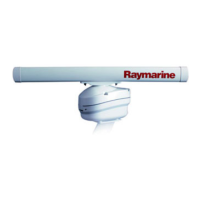
Details the process of marking, drilling, and securing the radar pedestal to the mounting surface.
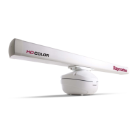
Guides on attaching the open array antenna to the pedestal, emphasizing caution.
Guides on initial setup, checking transmission, bearing alignment, and display timing.
Identifies common problems, their causes, and corrective actions for the radar system.
Explains the meaning of VCM100 status LED indicators for troubleshooting.
| Frequency | 9.41 GHz |
|---|---|
| Power Output | 4 kW |
| Display | Color LCD |
| Beamwidth | 1.1° |
| Antenna Size | 72 inches |
| Antenna Length | 72 inches |
| Rotation Speed | 24/48 rpm |
| Input Voltage | 12/24 V DC |