Do you have a question about the Raytheon Anschütz Pilotstar D and is the answer not in the manual?
Describes the PILOTSTAR D autopilot system, its steering modes, and main components.
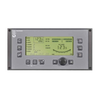
Details the operator unit's keys, display, and functional fields.
Lists the constituent PCBs and system extension capabilities of the connection unit.
Explains how the feedback unit converts rudder movement into an analog voltage.
Explains the autopilot's core principles for heading and track control.
Explains how to set and change the heading using the rotary knob or keys.
Describes using constant heading changes for maneuvers like fishing or towing.
Details operating with a navigation system for set heading via serial interface.
Explains track control mode using an external navigation receiver (e.g., GPS).
Describes the autopilot's monitoring electronics for alarms and sensor availability.
Discusses TRIM mode for low-speed operations and specific applications.
Details recommended applications for the TRIM mode.
Explains connecting additional operator units, tillers, and repeaters.
Explains connecting additional operator units as secondary steering stations.
Details the options for tiller control (FU/NFU) and their functions.
Describes integrating the autopilot with a central alarm system.
Mentions outputs for connecting rudder-angle indicators.
Explains connecting digital navigation data indicators.
Describes using the serial output for steering repeaters.
Lists technical specifications including electrical data and ambient conditions.
Lists power consumption, supply, enclosure types, and temperature ranges.
Details input and output interfaces for NMEA 0183 data.
Provides safety precautions and checks before operation.
Classifies the autopilot as a secondary steering system and notes quality assurance.
Lists required checks for power supply, steering gear, and sensors.
Describes how the ship follows heading input and potential rate of turn variations.
Outlines checks like comparing heading indications and setting the steering mode selector.
Explains how to change heading sensors and correct potential deviations.
Describes key functions, indications, and effects on steering control.
Defines symbols for key actuation, LED states, and audible signals.
Details requirements for track control, including track planning.
Shows a survey of possible operating conditions and modes based on mains connection.
Describes the STANDBY mode indication and its conditions.
Explains activating the autopilot via the steering mode selector in AUTO.
Details activating heading control and its display indications.
Describes how to change the SET HEADING using keys or the rotary knob.
Explains the automated SET HEADING change function for specific maneuvers.
Details remote operation via a navigation system.
Explains track control operation, including approaching and changing tracks.
Describes the steps for approaching a track before activating track control.
Explains how to initiate track changes via an external navigation system.
Details track course adjustment when using a position receiver with XTE.
Explains switching to and using manual control mode.
Details the TRIM function for reduced speed operations.
Explains how to adjust key and LCD illumination.
Describes performing an automatic lamp test.
Explains how to adjust operational parameters for different conditions.
Explains initial parameter adjustments and their effect on controller characteristics.
Guides on test runs for optimizing heading control parameters.
Provides recommended parameter values for different sea conditions.
Details how to set the monitoring limit for track deviations.
Explains setting the monitoring limit for heading deviations.
Describes how to adjust the maximum permissible rudder position.
Guides on adjusting track controller gain for optimal performance.
Explains synchronizing the autopilot with a gyro compass.
Explains adjusting ship-specific parameters and storing them.
Details how to adjust parameters like XTE TRIM and S_LENGTH.
Covers switching between operator units and tiller control.
Explains switching between main and secondary operator units.
Describes switching to tiller control and its implications.
Explains system messages, warnings, notes, and disturbed operations.
Explains how warnings and notes are displayed and indicated.
Lists possible warnings, their meanings, causes, and measures.
Explains possible notes displayed in the text line.
Defines disturbed operation and how fault messages are handled.
Describes acknowledging alarms via a central alarm system.
Shows a table of fault messages, causes, effects, and measures.
Provides safety precautions for handling electrostatic-sensitive semiconductor devices.
Discusses safety classifications and quality assurance.
Lists pre-operation checks for power, steering, and sensors.
States that the system requires no care and is maintenance-free.
Describes procedures for exchanging fuses, performing hardware resets, and exchanging PCBs.
Details the process of replacing a fuse in the connection unit.
Explains how to perform a hardware reset using the service switch.
Describes the procedure for removing and inserting PCBs.
Explains the function and meaning of LEDs on the CPU PCB.
Provides block diagrams and test points for PCBs.
Provides a block diagram of the I/O PCB and its connections.
Lists test points on the I/O PCB and their significance.
Shows a block diagram of the CPU PCB and its interfaces.
Reiterates safety precautions regarding electrical shock.
Lists pre-operation checks for power, steering, and sensors.
Instructs on checking equipment parts for damage after delivery.
Provides requirements for mounting operator, connection, and feedback units.
Details mounting requirements for the operator unit.
Specifies mounting requirements for the connection unit.
Outlines mounting requirements for the feedback unit, including linkage and belt transmission.
Refers to connection diagrams and passing cables through ferrite absorbers.
Explains adjusting ship-specific parameters and storing them.
Details how to adjust parameters like XTE TRIM and S_LENGTH.
Describes releasing the cold start to reset parameters to default values.
Details the steps to perform a cold start via software and service codes.
Provides a comprehensive procedure for initial power-up and testing.
Covers the installation and adjustment of the feedback unit.
Explains how to connect a voltmeter and balance the feedback potentiometer.
Details adjusting port and starboard limit switches for the feedback unit.
Describes adjusting the electrical zero point (offset) on the I/O PCB.
Guides on adjusting and testing the electrical rudder scaling.
Explains how to adjust and check the rudder slack parameter.
Details the procedure for adjusting the magnetic sonde.
Explains adjusting the flux-gate compass sonde.
Outlines the steps for conducting sea trials and parameter adjustments.
Provides a table guiding parameter setting based on condition and purpose.
Refers to Annex 1 for Operator Unit details.
Refers to Annex 2 for parameter information.
Refers to Annex 3 for parameter management.
Refers to Annex 4 for service parameter management.
| Brand | Raytheon Anschütz |
|---|---|
| Model | Pilotstar D |
| Category | Autopilot System |
| Language | English |