1
2
3
4
5
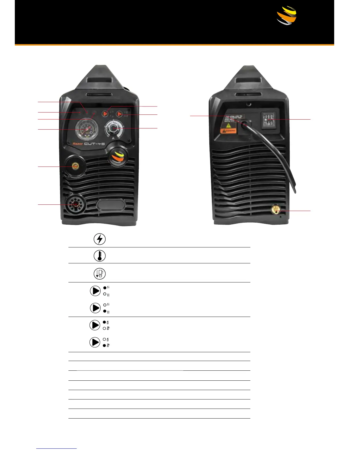
Power indicator It illuminates when the machine is powered on,
and it glitters after arc is successfully ignited.
:
Overheating indicator It illuminates when the working temperature
of the IGBT is overly high. Meanwhile, the machine stops working.
:
Torch protection indicator It illuminates when the consumable
parts of the machine are not well installed or the torch head is
shorted. Meanwhile the machine stops working.
:
2T indicator It illuminates when the machine is under 2T status.
6
Air Pressure Gauge
7
Amperage Control Dial.
8
Output connector (DC+) connect to the work piece.
9
Torch connection (DC-).
10
Primary power input cable.
11
On/Off switch.
12
Air supply connector
:
4T indicator: It illuminates when the machine is under 4T status.
Gas-check indicator It illuminates when the machine is under
gas-check status. At this moment, the machine cannot cut.
:
Normal cutting mode, the machine can cut when this
indicator illuminates.
: