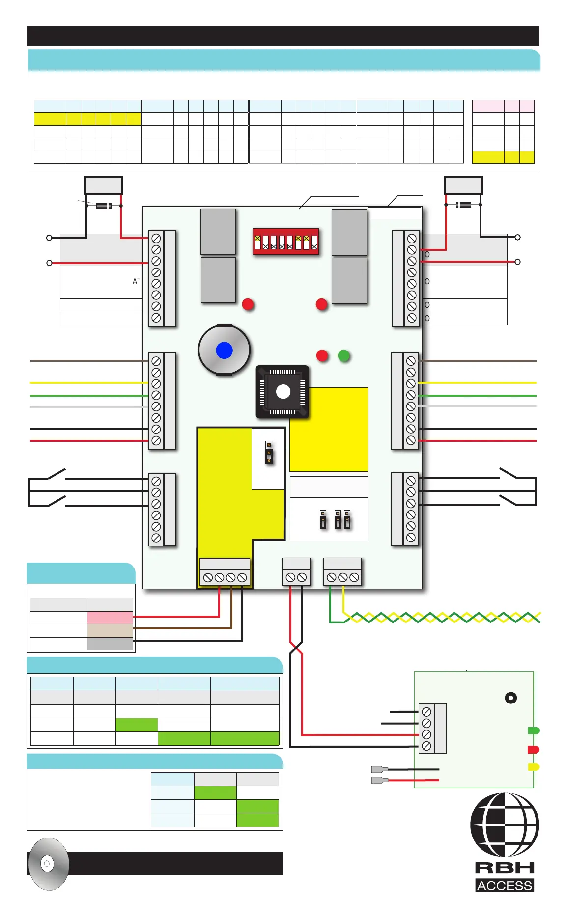
Output 1 Lock “A”
Output 2 Alarm shunt “A”
Output 3
Output 4
Output 5 Lock “B”
Output 6 Alarm shunt “B”
Output 7
Output 8
1 2 3 4 5 6 7 8
IRC-2000-5
158
JP1
JP2 JP3 JP4
P1 Outputs 1- 4
P2 Outputs 5 - 8
P3 Reader A
P4 Reader B
P5 Inputs 1- 4
P6 Inputs 5 - 8
P7
P8 P9
IRxxxxxxx
LED1 LED2
LED3 LED4
All jumpers off, change
only with tech support!
RS-485 BIAS
RS-232
RS-485
JP1 UP
if connector P7
is USED
JP1 DOWN
if NOT (Default)
Use RS-232 Cable on P7
to connect to a Serial port
on PC or LIF200 Network
Module, 50’ Max.
Verify it matches your
software, up/downgrade
as needed via Firmware
Upgrade Utility
FIRMWARE
Use Axiom Lite
software to check
firmware version
RX TX
See LED function
table below
Board model #
Serial #
Panel LEDs LED1 (Red) LED2 (Red) LED3 (Red) LED4 (Green)
FUNCTION Door forced Host Receive Transmit
OFF No Power is off Host not polling Panel not responding
ON SOLID Yes Online Malfunction Malfunction
BLINKING Card read Ofine Receiving Transmitting
Cycle power for DIP-switch changes to take effect!
A+ B- GND
Link up to 16 panels via RS-485
To 12 VDC 7 Ah
Rechargeable Battery
0VDC @ 2A
+12VDC @ 2A
PS-1224 Power Supply
BAT. TEST
Press “BAT. TEST” button on
PS-1224 for battery test, Yellow
LED will go ON if test failed
16.5VAC 40Va
16.5VAC 40Va
+ -
DCD
GND
RX
TX
1
C
2
3
C
4
RTE “A”- Request to Exit
DC “A” - Door contact
RTE “B”- Request to Exit
DC “B” - Door contact
5
C
6
7
C
8
GRN
RED
BUZ
D0
D1
TMP
0V
12V
LED (For single LED readers)
Buzzer
Data 0
Data 1
0V, Power, Data Ground
+12VDC
LED (For single LED readers)
Buzzer
Data 0
Data 1
0V, Power, Data Ground
+12VDC
GRN
RED
BUZ
D0
D1
TMP
0V
12V
N.O.
N.C.
COM
N.O.
N.C.
COM
OC
OC
Lock Power Supply
12-24 VDC
N.O.
N.C.
COM
N.O.
N.C.
COM
OC
OC
20-22 AWG Twisted, Shielded Pair. 4,000’ Max
Relay
Output 1
5A@30V
Relay
Output 2
5A@30V
Relay
Output 5
5A@30V
Relay
Output 6
5A@30V
Switch 1 2 3 4 5
Panel 1 On
Panel 2 On
Panel 3 On On
Panel 4 On
Switch 1 2 3 4 5
Panel 9 On On
Panel 10 On On
Panel 11 On On On
Panel 12 On On
Switch 1 2 3 4 5
Panel 13 On On On
Panel 14 On On On
Panel 15 On On On On
Panel 16 On
Switch 1 2 3 4 5
Panel 5 On On
Panel 6 On On
Panel 7 On On On
Panel 8 On
Switch 6 7
9.6 K
19.2 K On
38.4 K On
56 K On On
Switch 8: Always OFF!
12V 0V
THIS DOCUMENT IS FOR QUICK REFERENCE ONLY, REFER TO HARDWARE & SOFTWARE MANUALS FOR FULL DETAILS
RS-232 to PC or LIF-200
Panel LEDs
Power Supply (PS-1224) LEDs
DIP SWITCH SETTINGS : DIP-Switch: UP = ON / DOWN = OFF
DB9 RBH Cable
Pin 5 - GND Red
Pin 3 - TX Brown
Pin 2 - RX Black
50’ Max Shielded Cable Only
P7 P8
iButton
LED On Off
Green LED Power On Power Off
Red LED Shorted OK
Yellow LED Battery Fail Battery OK
Lock
+
Diode 1N4004
White stripe to +
-
For Support Call : 01386 425810
All software and hardware manuals are included
! on Axiom Lite software CD in “Documents” folder
Web site : www.rbhsecuritygroup.com E-mail : support.uk@rbh-access.com
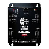
IRC-2000
Intelligent Reader Controller
with ENCL1 enclosure
and PS-1224 power supply
Lock Power Supply
12-24 VDC
+
-
Lock
Reader Shielding
Refer to hardware manual
Communications Shielding
Refer to hardware manual
Reader Color code
Refer to reader manual
Voltage (Open Collector) Outputs
-12VDC@100mA Max
Voltage (Open Collector) Outputs
Install diodes for rated relays
Belden 9538 cable for Readers
Belden 9538 cable for Readers
Belden 8723 cable for data
Belden 9538 cable for readers and Belden 8723 cable for data between panels
 Loading...