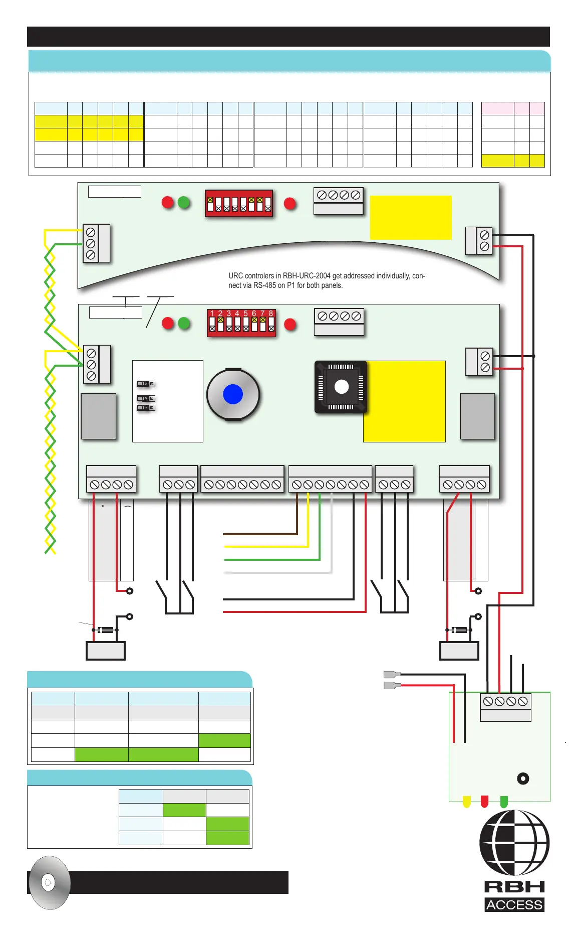
Panel LEDs LED1 (Red) LED2 (Green) LED3 (Red)
FUNCTION Receive Transmit Host
OFF Host not polling Panel not responding Power is off
ON SOLID Malfunction Malfunction Online
BLINKING Receiving Transmitting Ofine
Cycle power for DIP-switch changes to take effect!
To 12 VDC 7 Ah
Rechargeable Battery
0VDC @ 2A
+12VDC @ 2A
PS-1224
Power
Supply
BAT. TEST
Press “BAT. TEST” button
on PS-1224 for battery test,
Yellow LED will go ON if
test failed
16.5VAC 40Va
16.5VAC 40Va
Green LED
Buzzer
Data 0
Data 1
0V, Power, Data Ground
+12VDC
Switch 1 2 3 4 5
Panel 1 On
Panel 2 On
Panel 3 On On
Panel 4 On
Switch 1 2 3 4 5
Panel 9 On On
Panel 10 On On
Panel 11 On On On
Panel 12 On On
Switch 1 2 3 4 5
Panel 13 On On On
Panel 14 On On On
Panel 15 On On On On
Panel 16 On
Switch 1 2 3 4 5
Panel 5 On On
Panel 6 On On
Panel 7 On On On
Panel 8 On
Switch 6 7
9.6 K
19.2 K On
38.4 K On
56 K On On
Switch 8: Always OFF!
THIS DOCUMENT IS FOR QUICK REFERENCE ONLY, REFER TO HARDWARE & SOFTWARE MANUALS FOR FULL DETAILS
Panel LEDs
Power Supply (PS-1224) LEDs
DIP SWITCH SETTINGS : DIP-Switch: UP = ON / DOWN = OFF
LED On Off
Green LED Power On Power Off
Red LED Shorted OK
Yellow LED Battery Fail Battery OK
For Support Call : 01386 425810
All software and hardware manuals are included
! on Axiom Lite software CD in “Documents” folder
Web site : www.rbhsecuritygroup.com E-mail : support.uk@rbh-access.com
URC-2002
Universal Reader Controller
with ENCL1 enclosure
and PS-1224 power supply
Communications
Shielding
Refer to hardware
manual
Reader Color code
Refer to reader manual
Output 1 Lock Door “B”
Output 2 (100mA max.)
Output 3 Lock Door “B”
Output 4 (100mA max.)
URC-2000-4
P2 Outputs
URxxxxxxx
LED3LED1 LED2
JP1- RS-485
Termination
JP2
JP3
All jumpers off, change
only with tech support!
RS-485 BIAS
158
FIRMWARE
Use Axiom Lite software
to check firmware
version Verify it matches
your software, up/
downgrade as needed
via Frmware Upgrade
Utility
RX TX
A+
B-
GND
1
C
2
N.O.
N.C.
COM
0V
20-22 AWG
Twisted,
Shielded Pair.
4,000’ Max.
Relay
Output 1
5A@30V
Relay
Output 3
5A@30V
RTE “A”- Request to Exit
DC “A”- Door contact
DIAG
LED
BUZ
D0
D1
A
0V
12V
LED
BUZ
D0
D1
A
0V
12V
N.O.
N.C.
COM
0V
3
C
4
-12V
D+
D-
+12V
P4 Reader A P5 Reader B P7 OutputsP3 Inputs P6 Inputs
RTE “B”- Request to Exit
DC “B”- Door contact
Lock Power
12-24 VDC
+
-
P1
RS485
12v
0v
+
-
P9 Exp. Bus
URC controlers in RBH-URC-2004 get addressed individually, con-
nect via RS-485 on P1 for both panels.
iButton
URC-2000-4
URxxxxxxx
LED3LED1 LED2
RX TX
Serial #
A+
B-
GND
DIAG
-12V
D+
D-
+12V
P1
RS485
12v
0
v
+
-
P9 Exp. Bus
Model #
1 2 3 4 5 6 7 8
1 2 3 4 5 6 7 8
URC-2004 contains 2 URC-2000-4 boards
Link up to 16 panels via RS-485
Add up to 4 ELV8 out-
put boards in Elevator
Control Conguration
(RBH-URC-2008)
See LED function
table below
Lock
Diode 1N4004
White stripe to +
+
-
Lock
Belden 9538 cable for readers and Belden 8723 cable for data between panels
 Loading...