DOMINATOR INSTALLATION AND OPERATION INSTRUCTIONS Page 29
11. Turn the knob on the pilot valve to on, Figure 18.
12. Turn the knob on the main gas valve to on, 300 and
400 models, Figure 18. On 600 through 2100
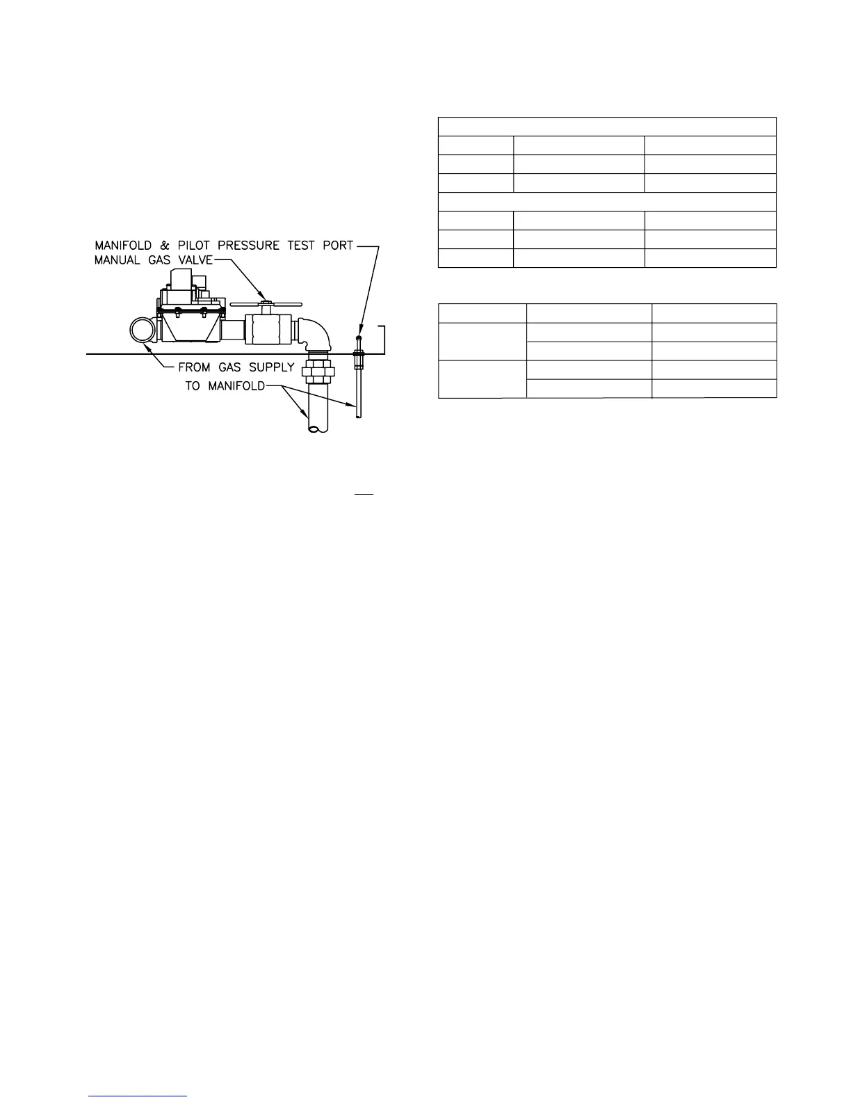
models open the manual shutoff valve located in the
control compartment, Figure 19.
13. Turn on all electric power to the boiler.
Figure 19 - Manual Valve & Manifold Pressure Tap
14. Set the staging control or thermostat to the desired
setting.
15. The pilot should automatically light. Do not try to
light the pilot by hand!
16. The burners should light with proper boiler
operation.
17. The pilot and manifold pressures should
match those listed in Table 19. To adjust the
manifold gas pressure see the “Gas Pressure
Adjustment” instructions in the “CHECKING AND
ADJUSTMENTS” section.
Required Gas Pressure
Provide gas supply pressure at inlet to boiler gas train
as follows:
LP Nat
Minimum (in W.C.) 11 6
Maximum (in W.C.) 14 14
Measure pressure when the boiler is fi ring at full rate.
Low gas pressure could indicate undersized gas line or
insuffi cient gas supply.
"Static and operating gas pressure required at the gas
valve inlet is between 6" W.C. and 14" W.C. for natural
gas and 11" W.C. and 14" W.C. for propane. If the gas
pressure is above this limit, a lock-up style regulator
suitable for dead end service such as an Equimeter
or Fisher must be installed to prevent increase (creep)
of gas pressure when the units are not operating.
This pressure regulator (supplied by others) may be
installed at the service entrance to each unit or a
"master" regulator sized to handle multiple units may
be utilized. Consult local gas utility or regulator
manufacturer for recommendations to meet specifi c job
site requirements."
Table 19 - Pilot & Manifold Settings
Table 20 - Combustion Readings
Instructions De Mise En Marche
1. ARRÊTEZ! Lisez les instructions de sécurité sur la
portion supérieure de cette étiquette.
2. Réglez le thermostat à la température la plus basse.
3. Coupez l'alimentation électrique de l'appareil.
4. Cet appareil est muni d'un dispositif d'allumage qui
allume automatiquement la veilleuse. Ne tentez pas
d'allumer la veilleuse manuellement.
5. Fermer la vanne manuelle d'arrêt d'alimintation de
gaz.
6. Attendre cinq (5) minutes pour laisser échapper tout
le gaz. Renifl ez tout autour de l'appareil, y compris
près du plancher, pour déceler une odeur de gaz.
Si vous sentez une odeur de gaz, ARRÊTEZ!
Passez à l'étape B des instructions de sécurité sur
la portion supérieure de cette étiquette. S'il n'y a pas
d'odeur de gaz, passez à l'étape suivante.
7. Ouver la vanne manuelle d'arrêt d'alimintation de
gaz.
8. Mettez l'appareil sous tension.
9. Réglez le thermostat à la température désirée.
10. Si l'appareil ne se met pas en marche, suivez les
instructions intitulées couper l'admission de gaz de
l'appareil et appelez un technicien qualifi é ou le
fournisseur de gaz.
To Turn Off Gas To Appliance
1. Set the operating control or thermostat to its lowest
setting.
2. Turn off all electric power to the appliance if service
is to be performed.
3. Close the manual main valves.
COUPER L'ADMISSION DE GAZ DE L'APAREIL
1. Réglez le thermostat à la température la plus basse.
2. Coupez l'alimentation électrique de l'appareil s'il faut
procéder à l'entretien.
3. Fermer la vanne manuelle d'arrêt d'alimintation de
gaz.
Natural Gas
inches W.C. mm W.C.
Low Fire 1.5 ± 0.2 33 ± 5
High Fire 2.5 ± 0.2 63 ± 5
LP Gas
inches W.C. mm W.C.
Low Fire 3.9 +/- 0.2 99 ± 5
High Fire 9.3 +/- 0.2 236 ± 5
Natural Fuel Propane Fuel
CO
2
%
7.0 – 7.5 (low) 8.2 – 8.8 (low)
7.8 – 8.5 (high) 9.2 – 9.9 (high)
O
2
%
8.3 – 7.6 (low) 8.3 – 7.6 (low)
7.0 – 5.8 (high) 7.0 – 5.8 (high)

 Loading...


