SPECTRUM INSTALLATION AND OPERATING INSTRUCTIONSPage 16
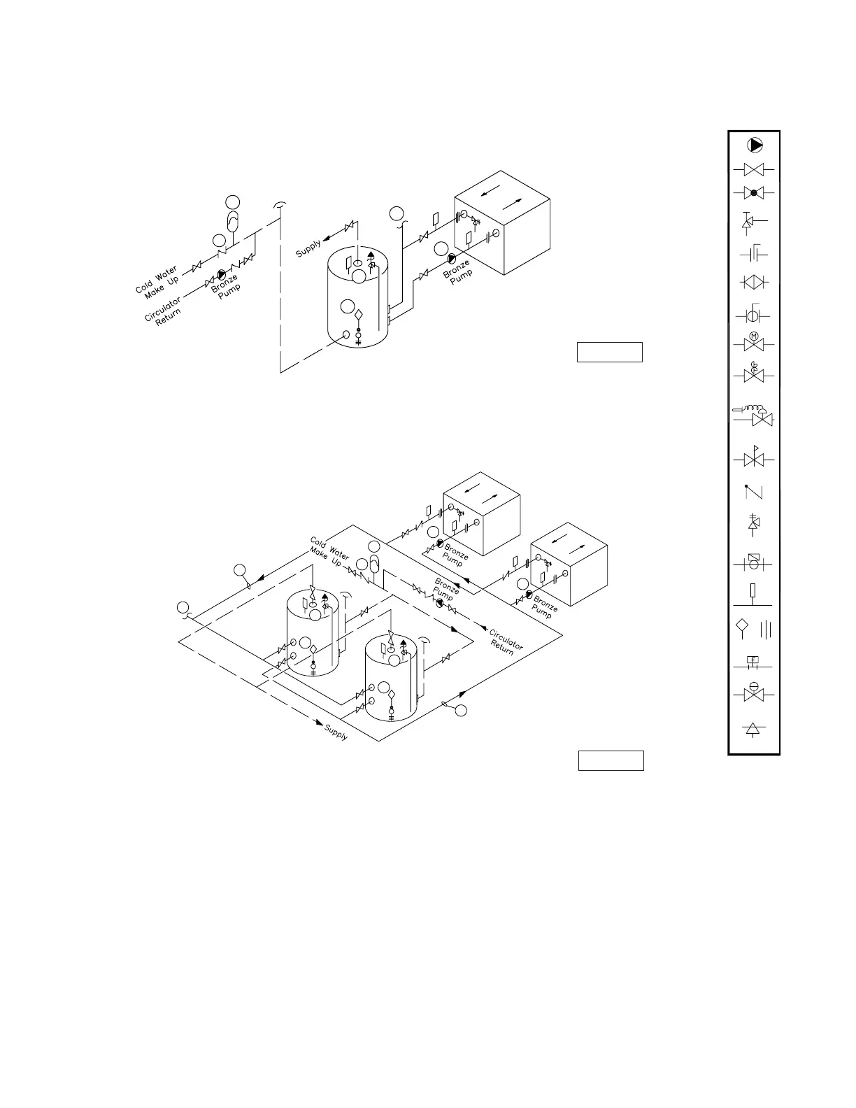
Figure 8 - Typical Water Heating Piping (SW Models Only)
(See Notes)
Operated Valve
Air Vent
Pressure Switch
Aquastat Union
Gas Pressure
Regulator
Automatic
Thermometer
Flow Switch
Pressure
Relief Valve
Reducing Valve
Self-Operated
Check Valve
Pressure
Valve
Pump
Motorized Valve
Solenoid
Ball Valve
Bufferfly Valve
Angle Valve
Valve
Globe Valve
Balance Valve
2
3
1
4
7
8
Figure 9 - Multiple Water Heating Piping (SW Models Only)
(See Notes)
1
2
3
2
7
7
6
6
8
4
4
D-1 Rev 4
D-4 Rev 4
NOTES:
1. Optional cold water make up and recirculation line location.
2. When using intermittent pump and pump delay, locate remote
aquastat well in lower 1/3 of tank. Install bulb with heat
sensing compound.
3. Thermal expansion tank may be required, check local codes.
4. When using optional factory mounted pump, max pipe length
30' total, 6-90
˚
elbows, full pipe size.
5. CAUTION: MEASURE WATER HARDNESS AND pH AT JOB SITE.
The pH and water hardness must be determined before selecting
heat exchanger and pump. Consult the Heat Exchanger Graph and
Pumping Performance Table before making selection.
6. Common piping must be sized for maximum combined heater flow.
7. Hot water tanks should be equipped with a combination
temperature & pressure relief valve.
8. MA Code requires an 1/8'' hole in check valve to compensate for
thermal expansion.
Notice: These drawings show suggested piping configuration and valving.
Check with local codes and ordinances for specific requirements.
 Loading...