5
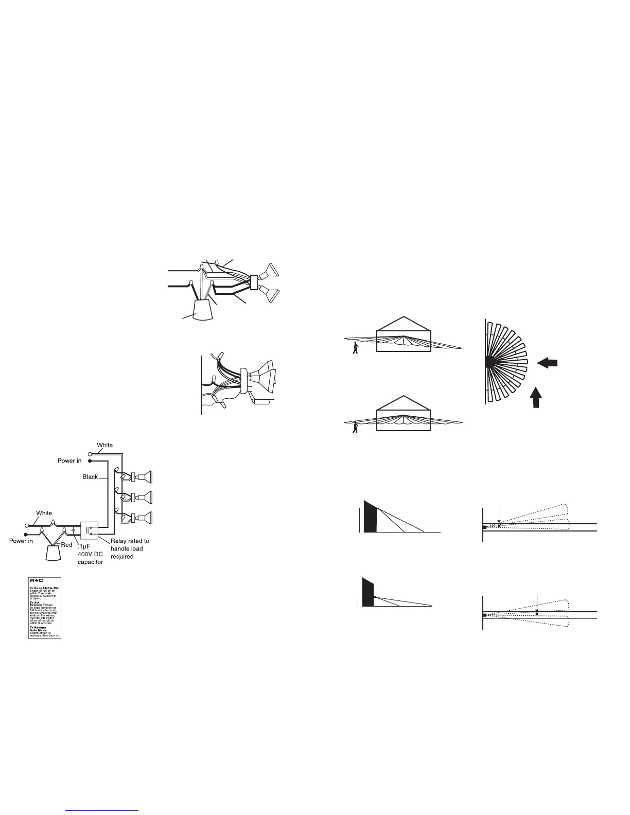
Basic Wiring Diagram
Basic Kit Wiring
Switchplate Label
Multiple fixtures may be wired to a
single sensor.
To handle loads greater than 1,000
watts, a qualified electrician
should install a relay.
Power Quality
It is not recommended to install
sensors on a circuit that also feeds
motor loads such as HVAC equip-
ment, kitchen appliances, or garage
door openers. The Stealth circuit is
surge and transient protected to
IEC specifications. However, if
voltage varies significantly from
120 volts, sensor may malfunction.
Wiring Diagrams
Black
Black
Red
Red
(pigtail)
Ground
Ground
White
White
Power In
Multiple Fixtures
Note: Pigtail is only used to switch
remote or additional light fixtures
Switchplate label with
self-adhesive backing.
Attach Stealth operating
instruction label to
switchplate for quick
and easy reference.
STL200
Power In
Sensor
Red
B
lack
White Ground
1. Check that the sensor is level
from side to side and pointed at the
area you desire. If unit is tilted, part
of the detection zone may be high
in the air over people’s heads.
Solution: Position sensor exactly
level from side to side.
2. Check that the sensor is not
mounted too high. If mounted
above 20 feet, much of the usable
range will be lost.
Solution: Mounting at 6 feet to
12 feet allows maximum range.
3. Check that movement is not
directly towards sensor. Sensor
will see movement across its
pattern more quickly. To fix,
move the sensor.
4. Check that movement far away
and directly towards sensor is not
entirely within one zone.
Problem:
Sensor will not detect until
movement crosses zones
Solution:
“Micro Adjust” sensor by moving
sideways 1/4". This may move the
zones to allow earlier detection.
Technical Tips:
Range Appears Limited
50'
40'
20'
6-12'
Less
Sensitive
More
Sensitive
10
WRONG!
OK!
No Detection Until Here
PATHWAY
Detection Much Sooner
PATHWAY