2
Connections
As
shipped the
microphone
is connected
for
an output
impedance
of
250
ohms.
To connect
the microphone
for an
output
impedance
of 30
or 150 ohms,
first lower
the
bottom cover
by
removing
the four
machine
screws around
the
rim of the
cover.
Pull the
cover
down
until
the transformer
terminal
board
connections
are
accessible.
For
the proper
cable
con-
nections,
refer to
figure 3.
Directional
Characteristics
The adjustable
shutter
over
the
slot in
the tube leading
to the
acoustic labyrinth
may be
rotated by means of a
screwdriver ad-
justment extending through
the rear
screen
flush with
a
designation plate.
The plate is marked U,
N and B,
as
symbols
for the
uni
-directional, non -directional
and
bi-
directional
patterns. Three additional
markings
L -1, L -2, and L -3
are used as
reference points
for
other
directional
patterns
which
may be obtained. Refer to
figure
4
for the
patterns
associated
with
each of the
six
symbols. Stops are provided
on the continuously -variable pattern selector
at the six marked
positions, although
the
shutter may
be
set
at any intermediate
position.
Frequency Response
At the bottom of
the lower
shell is
a
screwdriver
-operated selector
marked M (music)
V1 and V2 (voice).
The
voice
positions
connect a reactor
across
the entire
secondary
or part of the
secondary of
the output trans-
former,
depending on
the switch position
(see
diagram, figure
3).
Refer
to figure
5
for the
frequency-
response characteristics
of each
setting. As can be
seen from the curves,
the
reactor attenuates
the low-
frequency response.
This is especially
desirable
when
the
micro-
phone is less than
three feet
from the source
of
sound and the low-
frequency
response
would
otherwise
be exaggerated.
Phasing
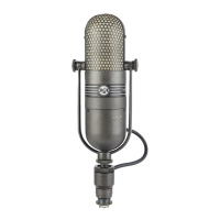
The Type 77 -DX Microphone
is phased
so that
the red cable lead
is electrically
positive
when
the
sound
pressure
on the front
of the
microphone is
in the
positive half
of the
cycle.
When
the
outputs of two
or more
microphones
are connected
into a
mixing circuit,
it is
necessary
that
the outputs
of
all
such
micro-
phones h 'ave
the same
phase relation.
Other-
wise,
the
output
of one
microphone
will
oppose
the
output of another,
resulting
in a
reduction
in
output, and
introducing
varying
degrees
of distortion.
To check
the
phasing
of
two or more
micro-
phones,
connect
one microphone
to
the associ-
ated
amplifier
input
and set
the
volume
control
to obtain
the desired
output, while
talking into
the
microphone.
Then,
connect
the
second
microphone
in parallel
with
the
first
and,
without
changing
the volume
control
setting, hold
both
microphones close
together
and
talk into
them. If
the
volume
decreases
from the
previous
level, reverse
the
connections
of
one of the
microphone
cables
at the
microphone
plug.
Check
each
additional
microphone
for
phasing
in this
manner, and,
if necessary,
reverse
the cable
connections
to
correct
the
phasing
to
agree
with
that
of the microphone
already
connected.
When the
sound source is
directed
toward
the back of the microphone,
there
will be a
large phase
shift
when
changing
the
pattern
selector from
bi- directional
to non-
direction-
al
or
the reverse.
The safest
way
to avoid
undesirable directional effects
resulting
from the
above
is
to set
microphones
operating
close to one another
on the
same
directional
response position,
or
at
least avoid
having
some
on
the non -directional
pattern
and
the
others
on
the
bi-
directional
pattern.
Directional
Setting
The proper
position
of the
pattern
se-
lector
depends
upon
the particular
instal-
lation.
The same
holds
true for
the
placement
of the microphone.
Consult
figure
4
for
the
directional
patterns
of
the six
reference
positions.
 Loading...