3
ENAMEL
FORMEX
SLEEI//NG
BBON
OREEN
YELLOW
RED
BLACK
S.D 50LCERE:,
To OCEEN'
LEAD -
áREEN
III
SLACK
rp
.ED
BLUE
T
L-+REFN
I- --I./
RED
VZ II'
BLACK
\'L /BLACK
YELLOW
YELLOWx
SLEEY/N,n -
BLACK
7-n977B-1
TYPE 77D
8,77DX
MICRGP'IONE
_ ORED
1
C. BLK. I j kED
1
GRN.
BLK.
;ì
j
SRN.
- 1501
(iLK.
RED
.IRN.
G50
CABLE
CONNECTIONS
M I- 4045
E aMe!
M/-404SF
MI - I 1 706 B
an!
MI-//006C
M -
149778
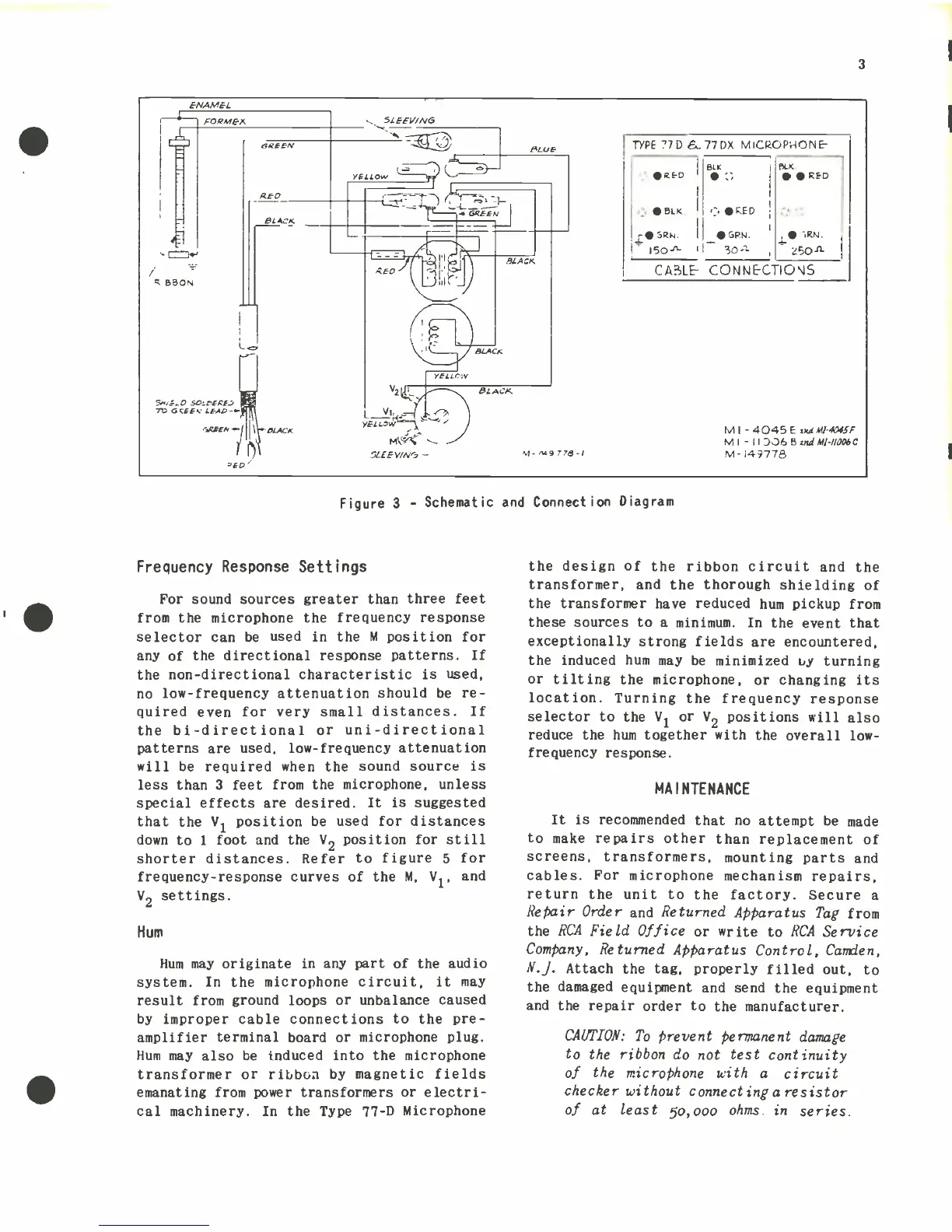
Figure 3 -
Schematic
and
Connection
Diagram
Frequency
Response
Settings
For sound sources greater than
three feet
from the microphone the frequency response
selector
can be
used in the M position
for
any of the
directional
response
patterns. If
the
non
-directional
characteristic is
used,
no
low- frequency
attenuation should be
re-
quired
even
for very
small
distances.
If
the bi-
directional
or uni-
directional
patterns
are
used,
low-
frequency attenuation
will
be required
when
the
sound source is
less than 3
feet from the microphone,
unless
special effects
are
desired. It is suggested
that the VI position
be
used for distances
down to
1
foot
and
the V2 position
for still
shorter distances. Refer to figure
5
for
frequency-
response curves of the
M, V1,
and
V2 settings.
Hum
Hum may originate in any part of
the
audio
system. In the microphone
circuit, it may
result
from
ground loops
or unbalance caused
by improper cable connections
to the
pre-
amplifier terminal board or
microphone plug.
Hum may also
be
induced
into
the microphone
transformer
or
ribbon
by magnetic
fields
emanating
from power transformers or electri-
cal machinery. In the Type
77
-D
Microphone
the
design of the
ribbon circuit
and the
transformer, and
the
thorough
shielding
of
the transformer
have
reduced
hum
pickup from
these sources
to a minimum. In
the
event
that
exceptionally strong fields
are
encountered,
the induced hum
may be minimized 6,y
turning
or tilting the microphone,
or changing
its
location. Turning
the frequency
response
selector to the VI
or
V2 positions
will
also
reduce the hum
together
with
the
overall low
-
frequency
response.
MAINTENANCE
It
is
recommended
that
no attempt
be made
to
make
repairs other than
replacement
of
screens,
transformers,
mounting
parts
and
cables.
For microphone
mechanism
repairs,
return
the unit
to the
factory. Secure
a
Repair
Order
and
Returned
Apparatus
Tag
from
the
RCA Field
Office
or
write
to
RCA
Service
Company,
Returned Apparatus
Control,
Carden,
N.J.
Attach
the
tag, properly filled
out, to
the
damaged
equipment and
send the
equipment
and
the repair
order to the
manufacturer.
CAUTION:
To
prevent
permanent
damage
to
the ribbon
do not test
continuity
of
the
microphone with
a circuit
checker
without connecting
a resistor
of
at
least
5o,000
ohms. in
series.
 Loading...