DCN 140-01761-01 3/21/09
8
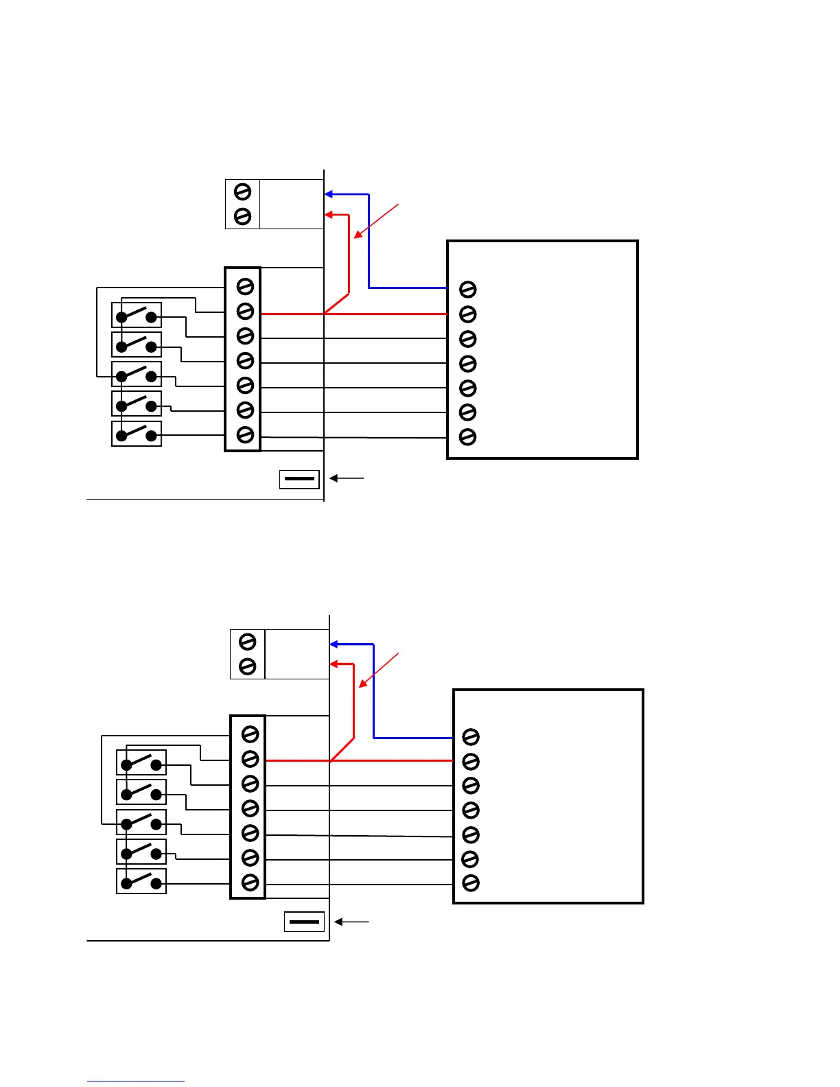
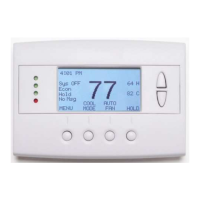
HVAC System Connection
The TR60 HVAC Control Unit connects to the HVAC system like a standard thermostat.
Standard Gas/Electric HVAC System Wiring
Heat Pump HVAC System Wiring
Standard HVAC System
G Fan
W 1 Heat Stage 1
Y1 Compressor Stage 1
R 24VAC RETURN
C 24VAC COMMON
Red
Green
White
Yellow
W1 Aux Heat
Y1 Compressor Stage 1
R 24VAC RETURN
C 24VAC COMMON
Heat Pump HVAC System
Red
Green
White
Yellow
THERMOSTAT CONNECTION
HVAC Control Unit
THERMOSTAT CONNECTION
HVAC Control Unit
Orange
O/B Changeover (CO) Valve
Y2 Compressor Stage 2
W1 HEAT
W2 Heat Stage 2
RH 24V
Y2 Compressor Stage 2
G Fan
JP1: RH and RC Jumper
This commons both RH and RC for normal single transformer HVAC systems.
Cut JP1 jumper for separate RH and RC transformer systems.
NOTE: When jumper JP1 is cut, W1 and W2 are switched to RH. G, Y1
and Y2 are switched to RC.
JP1
RC 24V
JP1
JP1: RH and RC Jumper . Do not cut.
Leave RH and RC connected for Heat Pump Systems
Orange
Brown
Brown
G FAN
HVAC System
Y2 COMP
G Fan
HVAC System
Y2 Comp
RC 24V
NOTE: Set correct Changeover
value operation for O (CO w/Cool)
or B (CO w/Heat) mode on
DIPSW1 on the control board.
Blue
Blue
24C
PWR
24R
24C
PWR
24R
Install jumper wire for power
from HVAC System
Install jumper wire for power
from HVAC System