Do you have a question about the Realistic DX-160 and is the answer not in the manual?
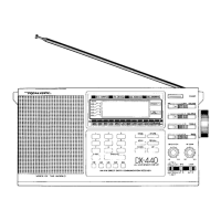
Details the assembly and positioning of knobs for various controls.
Illustrates the layout of internal components from the top of the chassis.
Explains the process of stringing the main tuning dial mechanism.
Details the stringing procedure for the band spread dial mechanism.
Provides a functional overview of the receiver's circuit blocks.
Shows the equivalent schematic representation of the integrated circuit.
Illustrates the pin layout and function for the integrated circuit.
Steps for aligning the Intermediate Frequency stages of the receiver.
Procedure for aligning the Radio Frequency stage for Band A.
Procedure for aligning the Radio Frequency stage for Band B.
Procedure for aligning the Radio Frequency stage for Band C.
Procedure for aligning the Radio Frequency stage for Band D.
Procedure for aligning the Radio Frequency stage for Band E.
Shows the component layout on the bottom side of the Printed Circuit board.
Illustrates the component placement on the bottom of the coil pack PCB.
Details the wiring connections for the coil pack printed circuit board.