Do you have a question about the Realistic DX-440 and is the answer not in the manual?
Detailed electrical performance specifications for the Shortwave (SW) band.
Detailed electrical performance specifications for the Frequency Modulation (FM) band.
Detailed electrical performance specifications for the Medium Wave (MW) band.
Detailed electrical performance specifications for the Long Wave (LW) band.
Steps to remove the unit's back cover for access.
Instructions for removing various Printed Circuit Boards (PCBs) like A-1, B, A-2, and C.
Diagram illustrating the overall system architecture and signal flow.
Description of the µPD7503G microcontroller and keyboard matrix.
Description of the LCD and the CX-7961A-1 frequency synthesizer PLL circuit.
Descriptions of AM/FM IF amplifier, FM MPX demodulator, and related ICs.
Descriptions of signal driver, pre-amplifier, and power amplifier ICs.
Procedures for aligning power supply VDD and clock time accuracy.
Procedures for aligning VC01 voltage range and PLL frequency.
Alignment procedures for AM 2nd Local OSC, AM 2nd IF, and AM sensitivity.
Alignment procedures for FM IF and FM sensitivity.
Procedures for aligning BFO, signal/stop levels, and MPX.
Troubleshooting steps for scan auto stop function issues.
Troubleshooting steps for weak reception sensitivity in FM and AM bands.
Troubleshooting steps for power-on and PLL circuit issues.
Diagram showing wiring connections on the PCB solder side.
Layout diagrams for various Printed Circuit Boards (PCBs).
Visual representation of the unit's components in an exploded format.
Comprehensive lists of components including exploded view, electrical, and voltage data.
Voltage values for integrated circuits and transistors.
Diagrams showing lead identification for semiconductors.
Complete circuit schematic diagram of the receiver.
| Dimensions | 260 x 155 x 55 mm (10.2 x 6.1 x 2.2 inches) |
|---|---|
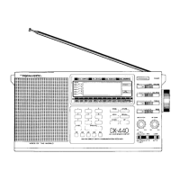
| Type | Portable Receiver |
| Modes | AM, FM, SW |
| Sensitivity (SW) | 10 µV |
| Power Supply | DC 6V (4 AA batteries or AC adapter) |
| Bands | AM, FM, SW |
| Sensitivity (FM) | 3 uV |
| Audio Output | Headphone Jack |