RTL8762D Evaluation Board User Manual
Copyright 2021 Realtek Semiconductor Corporation. All Rights Reserved.
12
1.2.7
Pin Allocation on Motherboard of Evaluation Board
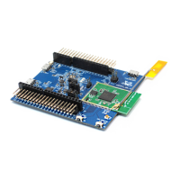
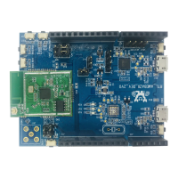
When edges of daughter board are flush with the white lines and PCB antenna on daughter board is aligned with
silkscreen mark on motherboard, the pins on daughter board are properly inserted; otherwise it is necessary to be
cautious about improper connection.
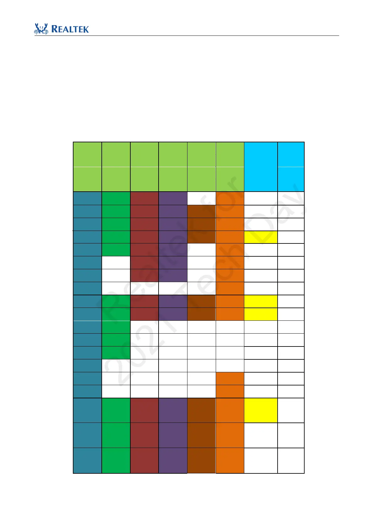
Pin allocation of motherboard is listed as follows:
Table 1.1 IO Pin Allocation on Motherboard & Daughterboard
RTL8752
EVB
FunctIO n
RTL8762
RTL8762
DJF RTL8762
RTL8762 RTL8762 EVB
DW DK RTL8762 DDF DGF DKF socket
DJF
P0_0 P0_0 P0_0 P0_0 P0_0 P0_0
M0_0
P0_1 P0_1 P0_1 P0_1 P0_1 P0_1 LED0 M0_1
P0_2 P0_2 P0_2 P0_2 P0_2 P0_2 LED1 M0_2
P0_3 P0_3 P0_3 P0_3 P0_3 P0_3 LOG M0_3
P0_4 P0_4 P0_4 P0_4 P0_4 P0_4
M0_4
P0_5 P0_5 P0_5 P0_5 P0_5 P0_5
M0_5
P0_6 P0_6 P0_6 P0_6 P0_6 P0_6
M0_6
P0_7 P0_7 P0_7 P0_7 P0_7 P0_7
M0_7
P1_0 P1_0 P1_0 P1_0 P1_0 P1_0 SWDIO M1_0
P1_1 P1_1 P1_1 P1_1 P1_1 P1_1 SWDCLK M1_1
P1_2 P1_2 P1_2 P1_2 P1_2 P1_2
M1_2
P1_3 P1_3 P1_3 P1_3 P1_3 P1_3 LED2 M1_3
P1_4 P1_4 P1_4 P1_4 P1_4 P1_4 LED3 M1_4
P1_5 P1_5 P1_5 P1_5 P1_5 P1_5
M1_5
P1_6 P1_6 P1_6 P1_6 P1_6 P1_6
M1_6
P1_7 P1_7 P1_7 P1_7 P1_7 P1_7
M1_7
MICBIAS
MICBIAS
MICBIAS
MICBIAS
MICBIAS
MICBIAS
MIC_BIA
S
M_MICB
IAS
32k_XI
32k_XI
32k_XI
32k_XI
32k_XI
32k_XI
M_32k_
XI
32k_XO
32k_XO
32k_XO
32k_XO
32k_XO
32k_XO
M_32k_
XO
Realtek for
2021 Tech Day