4” Standard Pump Installation, Operation & Service Manual Control Boxes
47
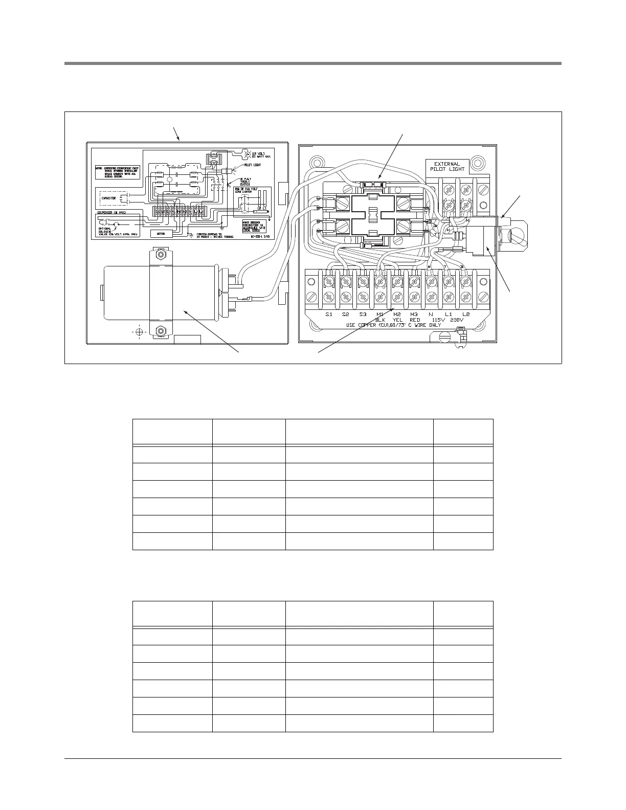
Figure 39. 880-045-5/880-046-5 control box
Table 13.- 880-045-5 1/3 & 3/4 HP Control Box w/Cap (115V Coil)
Item
(Ref. Figure 39) Part No. Description Qty.
1 123-141-1 Control box 1
2 147-006-1 Pilot light ass'y 1
3 014-723-1 Line contractor relay 1
4 080-858-1 Toggle switch 1
5 008-202-1 Terminal block 1
6 111-092-5 Capacitor 1
Table 14.- 880-046-5 All 1-1/2 HP Control Box w/Cap (115V Coil)
Item
(Ref. Figure 39) Part No. Description Qty.
1 123-141-1 Control box 1
2 147-006-1 Pilot light ass'y 1
3 014-723-1 Line contractor relay 1
4 080-858-1 Toggle switch 1
5 008-202-1 Terminal block 1
6 111-661-5 Capacitor 1
1
2
3
4
5
6
153-16.eps