CONFIGURING A G308
The G308 is configured using Crimson software. Crimson is available as a free
download from Red Lion’s website, or it can be purchased on CD. Updates to
Crimson for new features and drivers are posted on the website as they become
available. By configuring the G308 using the latest version of Crimson, you are
assured that your unit has the most up to date feature set. Crimson software can
configure the G308 through the RS232 PGM port, USB port, or CompactFlash.
The USB port is connected using a standard USB cable with a Type B
connector. The driver needed to use the USB port will be installed with Crimson.
If this driver has not been installed, it can be downloaded from the website.
The RS232 PGM port uses a programming cable made by Red Lion to
connect to the DB9 COM port of your computer. If you choose to make your
own cable, use the “G308 Port Pin Out Diagram” for wiring information.
The CompactFlash can be used to program a G3 by placing a configuration
file and firmware on the CompactFlash card. The card is then inserted into the
target G3 and powered. Refer to the Crimson literature for more information on
the proper names and locations of the files.
ETHERNET COMMUNICATIONS
Ethernet communications can be established at either 10 BASE-T or 100
BASE-TX. The G308 unit’s RJ45 jack is wired as a NIC (Network Interface
Card). For example, when wiring to a hub or switch use a straight-through cable,
but when connecting to another NIC use a crossover cable.
The Ethernet connector contains two LEDs. A yellow LED in the upper right,
and a bi-color green/amber LED in the upper left. The LEDs represent the
following statuses.
The Crimson manual contains additional information on Ethernet
communications.
CABLES AND DRIVERS
Red Lion has a wide range of cables and drivers for use with many different
communication types. A list of these drivers and cables along with pin outs is
available from Red Lion’s website. New cables and drivers are added on a
regular basis. If making your own cable, refer to the “G308 Port Pin Outs” for
wiring information.
ACCESSING THE COMPACTFLASH CARD
VIA USB DEVICE PORT
RS232 PORTS
The G308 has two RS232 ports. The G308A ports are individually isolated,
while the G308C ports are not isolated. There is the PGM port and the COMMS
port. Although only one of these ports can be used for programming, both ports
can be used for communications with a PLC.
The RS232 PGM port can be used for either master or slave protocols with
any G308 configuration.
Examples of RS232 communications could involve another Red Lion product
or a PC. By using a cable with RJ12 ends on it, and a twist in the cable, RS232
communications with another G3 product or the Modular Controller can
e
established. Red Lion part numbers for cables with a twist in them are
CBLPROG0
1
, CBLRLC01
2
, or CBLRC02
3
.
1
CBLPROG0 can also be used to communicate with either a PC or an ICM5.
2
DB9 adapter not included, 1 foot long.
3
DB9 adapter not included, 10 feet long.
In order to access data from the CompactFlash card via the USB device port,
a driver must be installed on your computer. This driver is installed with
Crimson and is located in the folder C:\Program Files\Red Lion Controls\
Crimson 2.0\Device\ after Crimson is installed. This may have already
een
accomplished if your G308 was configured using the USB port.
Once the driver is installed, connect the G308 to your PC with a USB cable,
and follow the “Mounting the CompactFlash” instructions found in the Crimson
user manual.
G3 RS232 to a PC
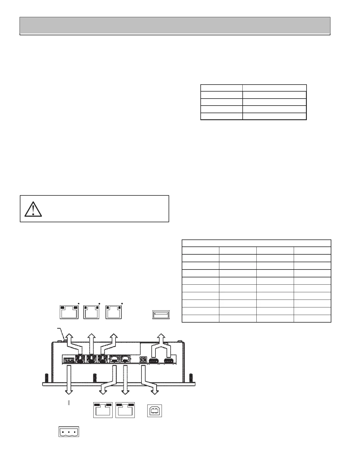
G308 PORT PIN OUTS
RS232
RS232
COMMS
PORT
COMMS
PORT
PGM PORT
USB HOST
(G308A only)
PROTECTIVE
EARTH GROUND
ETHERNET
(NIC)
AUXILIARY
ETHERNET
(OPTIONAL)
USB
TYPE B
POWER
CONNECTOR
4
TxA
(PIN
8)
TxB
COMM
TxEN
RxB
TxA
TxB
(PIN
1)
RTS
(PIN
6)
Tx
COMM
COMM
Rx
CTS
(PIN
1)
1
COMMON
2
24V
+
-
20%
3
N/C
RTS
(PIN
6)
Tx
COMM
COMM
Rx
CTS
(PIN
1)
1 2 3 4
RS485
Connections
G3: RJ12 Name PC: DB9 Name
4 COMM 1 DCD
5 Tx 2 Rx
2 Rx 3 Tx
N/C 4 DTR
3 COMM 5 GND
N/C 6 DSR
1 CTS 7 RTS
6 RTS 8 CTS
N/C 9 RI
WARNING - DO NOT CONNECT OR DISCONNECT CABLES
WHILE POWER IS APPLIED UNLESS AREA IS KNOWN TO BE
NON-HAZARDOUS. USB PORT IS FOR SYSTEM SET-UP AND
DIAGNOSTICS AND IS NOT INTENDED FOR PERMANENT
CONNECTION.
LED COLOR DESCRIPTION
YELLOW solid Link established.
YELLOW flashing Data being transferred.
GREEN 10 BASE-T Communications
AMBER 100 BASE-TX Communications
COMMUNICATING WITH THE G308
 Loading...