RS232 Communications
RS232 is intended to allow two devices to communicate over distances up to
50 feet. Data Terminal Equipment (DTE) transmits data on the Transmitted Data
(TXD) line and receives data on the Received Data (RXD) line. Data Computer
Equipment (DCE) receives data on the TXD line and transmits data on the RXD
line. The LD emulates a DTE. If the other device connected to the meter also
emulates a DTE, the TXD and RXD lines must be interchanged for
communications to take place. This is known as a null modem connection. Most
printers emulate a DCE device while most computers emulate a DTE device.
Some devices cannot accept more than two or three characters in succession
without a pause in between. In these cases, the meter employs a busy function.
As the meter begins to transmit data, the RXD line (RS232) is monitored to
determine if the receiving device is “busy”. The receiving device asserts that it
is busy by setting the RXD line to a space condition (logic 0). The meter then
suspends transmission until the RXD line is released by the receiving device.
RS485 Communications
The RS485 communication standard allows the connection of up to 32
devices on a single pair of wires, distances up to 4,000 ft. and data rates as high
as 10M baud (the LDA is limited to 38.4k baud). The same pair of wires is used
to both transmit and receive data. RS485 is therefore always half-duplex, that is,
data cannot be received and transmitted simultaneously.
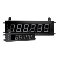
3.6 SERIAL WIRING
TBD
A
COMM
RXD
TXD
4
2
3
1
B
5
232
485
5
LD METER RECEIVING DEVICE
+5V
4
47K
47K
3
B (-)
A (+)
COMM.*
Transmit
Enable
* OPTIONAL
Terminal Block Connection Figure
1
TXD
RXD
COMM.
LD METER (DTE)
RECEIVING DEVICE
2
RXD
TXD
3
32
75
5
DTE
3
2
DB9
2
3
DTEDCE
DB25DB25
Terminal Block Connection Figure
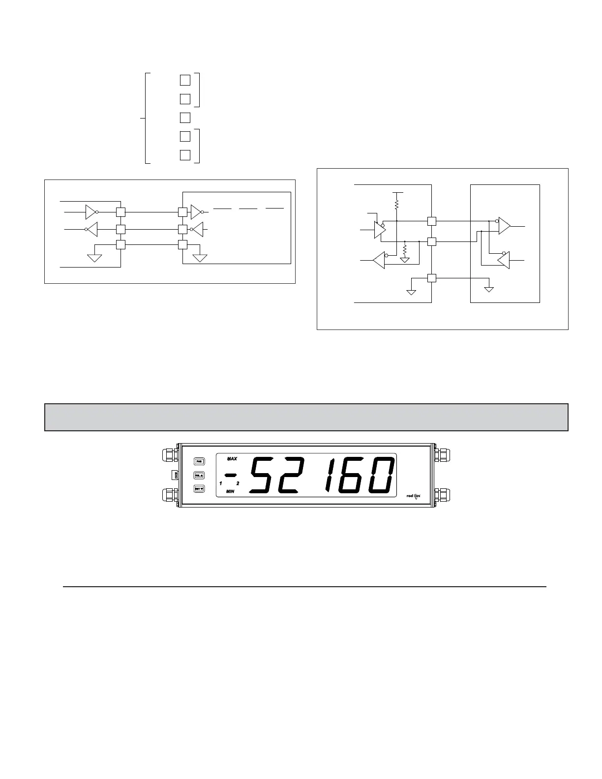
4.0 REVIEWING THE FRONT BUTTONS AND DISPLAY
BUTTON DISPLAY MODE OPERATION PROGRAMMING MODE OPERATION
PAR Access Programming Mode Store selected parameter and index to next parameter
RST
SEL
Resets display
Index display through selected displays
OPERATING MODE DISPLAY DESIGNATORS
MAX - Maximum display capture value
MIN
- Minimum display capture value
“1” - To the left of the display indicates setpoint 1 output activated.
“2” - To the left of the display indicates setpoint 2 output activated.
Pressing the SEL button toggles the meter through the selected displays. If display scroll is enabled, the display will toggle automatically every four seconds
between the enabled display values.
Advance through selection list/select digit position in
parameter value
Increment selected digit of parameter value
5
The serial connections are made via terminal block TBD located inside the
unit on the left side for the LD2 and on the right side for the LD4.

 Loading...