EasyManua.ls Logo

red lion LD User Manual

red lion LD
16 pages
To Next Page IconTo Next Page
Page #1 background imageLoading...
Page #1 background image
1
GENERAL DESCRIPTION
The Large Display Timer and Cycle Counter is a versatile display that
functions as an Elapsed Timer or Preset Timer, with full-featured user
programmability. The meter includes a built-in Cycle Counter, relay output and
serial communications capability. The 6 digit displays are available in either
2.25" or 4" high red LED digits with adjustable display intensity. The 2.25" high
models are readable up to 130 feet. The 4" high models are readable up to 180
feet. Both versions are constructed of a NEMA 4 enclosure in light weight
aluminum.
The Timer has two signal inputs and eight input operating modes. These
modes provide level active or edge triggered start/stop operation. The Timer
features 18 selectable timer ranges to cover a wide variety of timing
applications. The built-in Cycle Counter can be linked to timer operation to
count timing cycles, or function as a totally independent counter, accepting
count speeds up to 500 Hz. The display can be toggled either manually or
automatically between the Timer and Counter values.
In addition to the Timer/Counter inputs, a programmable User Input is
provided to perform a variety of meter functions. DIP switches are used to
configure the inputs for current sinking (active low) or current sourcing (active
high) operation.
The Setpoint Output can be assigned to the Timer or Counter value, and
configured to suit a variety of control and alarm requirements. The meter also
includes jumper selectable RS232 or RS485 serial communications.
SAFETY SUMMARY
All safety regulations, local codes and instructions that appear in this and
corresponding literature, or on equipment, must be observed to ensure personal
safety and to prevent damage to either the instrument or equipment connected to
it. If equipment is used in a manner not specified by the manufacturer, the
protection provided by the equipment may be impaired.
The protective conductor terminal is bonded to conductive
parts of the equipment for safety purposes and must be
connected to an external protective earthing system.
SPECIFICATIONS
1. DISPLAY: 2.25" (57 mm) or 4" (101 mm) intensity adjustable Red LED
2. POWER REQUIREMENTS:
AC Power:
AC Input: 85 to 250 VAC 50/60 Hz, 14 VA
DC Out: 11 to 16 VDC @ 50 mA (consult factory for higher current draw)
DC Power:
DC Input: 11 to 16 VDC @ 400 mA max, 7 W
3. TIMER DISPLAY: 6-digits
Display Range: 0 to 999999
Overflow/Underflow Indication: Display flashes “! #$%&
Minimum Digit Resolution: 0.001 Sec.
Maximum Single Digit Resolution: 1 Hr.
Timing Accuracy: ±0.01%
4. CYCLE COUNTER DISPLAY: 5-digits, may be disabled if not used
Display Designator: “
'” to the left side of the display
Display Range: 0 to 99999
Overflow/Underflow Indication: Display flashes “
' #$%&
! 2.25" or 4" HIGH RED LED DIGITS
! 6-DIGIT BI-DIRECTIONAL TIMING CAPABILITY
! 5-DIGIT CYCLE COUNTING CAPABILITY
! SELECTABLE TIMER RANGES AND OPERATING MODES
! ELAPSED TIMER AND PRESET TIMER FUNCTIONALITY
! SERIAL COMMUNICATIONS (SELECTABLE RS232 or RS485)
! PROGRAMMABLE USER INPUT
! AC OR DC POWERED
! 5 AMP FORM C RELAY OUTPUT
! ALUMINUM NEMA 4X CASE CONSTRUCTION
MODEL LD - LARGE DISPLAY TIMER AND CYCLE COUNTER
DIMENSIONS In inches (mm)
Bulletin No. LDT-B
Drawing No. LP0634
Released 9/06
Tel +1 (717) 767-6511
Fax +1 (717) 764-0839
www.redlion.net
X (Length)
LD2T06P0 16 (406.4)
LD4T06P0 26 (660.4) 7.875 (200)
CAUTION: Risk of Danger.
Read complete instructions prior to
installation and operation of the unit.
CAUTION: Risk of electric shock.
12 (304.8)4 (101.6)
C
US LISTED
US LISTED
U
L
R
IND. CONT. EQ.
51EB
PART
NUMBER
Z (Center)Y (Height)
22 (558.8)

Other manuals for red lion LD

Question and Answer IconNeed help?

Do you have a question about the red lion LD and is the answer not in the manual?

red lion LD Specifications

General IconGeneral
Brandred lion
ModelLD
CategoryTimer
LanguageEnglish

Summary

GENERAL DESCRIPTION

SAFETY SUMMARY

SPECIFICATIONS

DISPLAY SPECIFICATIONS

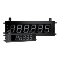
Details on LED digit size, intensity adjustment, and readability.

POWER REQUIREMENTS

Specifies AC and DC power input voltage, frequency, and consumption.

TIMER DISPLAY SPECIFICATIONS

Information on timer digit count, range, resolution, and accuracy.

CYCLE COUNTER DISPLAY SPECIFICATIONS

Information on counter digit count, range, and overflow indication.

DIMENSIONS In inches (mm)

1.0 INSTALLING THE METER

INSTALLATION ENVIRONMENT

Guidelines for safe installation regarding temperature, cleaning, and placement.

ORDERING INFORMATION

2.0 SETTING THE DIP SWITCHES

DIP SWITCH FUNCTIONS AND CONFIGURATION

Detailed explanation of each DIP switch's purpose and configuration options.

3.0 WIRING THE METER

EMC INSTALLATION GUIDELINES

Guidelines for proper installation and wiring to ensure EMI compatibility.

WIRING OVERVIEW

WIRING OVERVIEW

Overview of electrical connections made via pluggable terminal blocks.

POWER WIRING

Details on connecting AC and DC power to the unit's terminal block.

USER INPUT WIRING

Wiring for the Reset/User Input and Input Common terminals.

SETPOINT (OUTPUT) WIRING

Wiring for the setpoint relay output terminal block.

INPUT AND SERIAL WIRING

INPUT WIRING

Wiring configurations for the two signal inputs (A and B).

SERIAL WIRING

Instructions for configuring and wiring RS485 or RS232 serial communications.

4.0 REVIEWING THE FRONT PANEL KEYS AND DISPLAY

FRONT PANEL KEYS AND DISPLAY MODES

Description of the front panel keys (PAR, SELA, RSTV) and display modes.

5.0 PROGRAMMING THE METER

PROGRAMMING MENU STRUCTURE OVERVIEW

Overview of the meter's programming menu, modules, and parameters.

PROGRAMMING MODE ENTRY AND NAVIGATION

How to enter and navigate programming modes, modules, and parameters.

SELECTION AND VALUE ENTRY METHODS

Using SELA and RST keys to select and enter parameter values.

5.1 MODULE 1 - TIMER Input Parameters (1-IИP)

TIMER OPERATION AND RANGE CONFIGURATION

Settings for timer range, input operation modes, and filter settings.

TIMER START/STOP, INDICATORS, AND RUN STATE

Configuration of timer start/stop values, run indicator, and run state.

TIMER RESET AND USER INPUT FUNCTIONS

Settings for timer reset at power-up and user input function assignment.

5.2 MODULE 2 - CYCLE COUNTER PARAMETERS (2-CИt)

CYCLE COUNTER ENABLE AND COUNTING DIRECTION

Enabling the cycle counter and setting its counting direction.

CYCLE COUNTER COUNT SOURCE AND START VALUE

Selecting the count source and setting the initial start value.

CYCLE COUNTER RESET AT POWER-UP

Programming the cycle counter to reset automatically on power-up.

5.3 MODULE 3 - DISPLAY AND Front Panel KEY PARAMETERS (3-d5P)

FRONT PANEL DISPLAY SELECT AND RESET ENABLE

Enabling SELA for display toggle and RST for value reset.

DISPLAY SCROLL AND INTENSITY LEVEL SETTINGS

Configuring display scrolling and adjusting intensity levels (1-5).

PROGRAMMING SECURITY CODE AND FACTORY DEFAULTS

Setting security codes and loading factory default settings for the meter.

5.4 MODULE 4 - SETPOINT OUTPUT PARAMETERS (4-5PE)

SETPOINT ASSIGNMENT AND OUTPUT ACTION

Assigning setpoints and selecting output action modes (Latched, Timed, On-Off).

SETPOINT OUTPUT TIME-OUT AND STOP TIMER CONFIGURATION

Configuring output time-out duration and timer stop conditions.

AUTO RESET, DISPLAY RESET, AND POWER-UP STATE

Settings for auto reset, display reset interaction, and power-up state.

5.5 MODULE 5 - SERIAL COMMUNICATIONS PARAMETERS (5-5Er)

BAUD RATE, DATA BIT, AND PARITY BIT CONFIGURATION

Serial communication settings for baud rate, data bits, and parity.

METER ADDRESS AND ABBREVIATED PRINTING

Setting meter address for RS485 and configuring abbreviated data printing.

PRINT OPTIONS SELECTION

Selecting which meter parameters are included in print output requests.

Sending Serial Commands and Data

COMMAND CHART, CONSTRUCTION, AND RESPONSE

Overview of commands, their construction, and expected response times.

RECEIVING DATA FROM THE METER

Explanation of how to interpret data received from the meter in various formats.

COMMAND RESPONSE TIME AND COMMUNICATION FORMAT

COMMAND RESPONSE TIME AND TIMING DIAGRAM

Timing parameters for serial command processing and response illustration.

COMMUNICATION FORMAT AND DATA BITS

Details on data transfer format, start bits, data bits, parity, and stop bits.

Related product manuals