7
5.1 MODULE 1 - TIMER INPUT
PARAMETERS (
/0.*()
PARAMETER MENU
"
#
111111
&2*3%
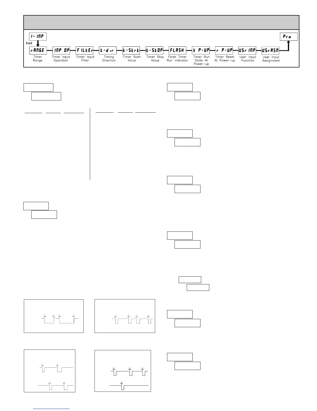
This parameter determines how the Timer Input Signals affect the Run/Stop
status of the Timer. Timing diagrams are shown below for level active and edge
triggered (1-input or 2-input) operation. For single input modes (Input A only),
Input B provides a level active Timer Inhibit function. In the Display Hold
mode, the timer display value remains held and only updates when a Timer
Start (Input A) or Timer Stop (Input B) edge occurs.
The timer reset (&+!) operating modes are identical to the other modes in the
diagrams, except the timer display value is reset at the Time Start edges.
The Timer can also be stopped at a Timer Stop Value or at Setpoint output
activation or deactivation. This type of Stop condition is cleared when a Timer
Reset occurs, or another start edge is applied on the timer input.
For Reset Modes (&+!), the timer is reset at Time Start edge.
18 TIMER RANGE SELECTIONS
(+ = SEC; * = MIN; 4 = HR; 5 = DAY
)6
TIMER RANGE
"
#
-%$%-
.*( #(
Level Active (Gated) Operation
INPUT A
INPUT B - Timer Inhibit (Level Active)
Time
Start
Time
Stop
Time
Start
Time
Stop
Edge Triggered Operation -1 Input
INPUT A
INPUT B - Timer Inhibit (Level Active)
Time
Start
Time
Stop
Time
Start
Time
Stop
%57%0/, %&+!0/
-%$%-, -%$&+!
TIMER INPUT OPERATION
4444,44 7777,77
0.01 HR
444444 777777
1 HR
44444,4 77777,7
0.1 HR
HOURS
*****,* 77777,7
0.1 MIN
****,** 7777,77
0.01 MIN
MINUTES
****** 777777
1 MIN
1111,11 7777,77
0.01 SEC
111,111 777,777
0.001 SEC
111111 777777
1 SEC
11111,1 77777,7
0.1 SEC
MAXIMUM
DISPLA
Y
DISPLAY
RESOLUTION
RANGE
SELECTION
SECONDS
DAYS/HOURS/MINUTES
55,44,** 77,89,17
1 MIN
44,**,++ 77,17,17
1 SEC
HOURS/MINUTES/SECONDS
444,**,* 777,17,7
0.1 MIN
44,**,** 77,17,77
0.01 MIN
HOURS/MINUTES
4444,** 7777,17
1 MIN
**,++,++ 77,17,77
0.01 SEC
****,++ 7777,17
1 SEC
***,++,+ 777,17,7
0.1 SEC
MAXIMUM
DISPLA
Y
DISPLAY
RESOLUTION
RANGE
SELECTION
MINUTES/SECONDS
-%$&+!
-%$%-
%&+!0/
%57%0/
4&+!08
4#-508
%&+!08
%57%08
#* #::
TIMING DIRECTION
Bi-directional timing capability. Select the timing direction desired for the
application.
;;;;;; to 777777
"
#
#*
:.-!%&
"
#
<(
!05=&
"
#
;;;;;;
!0+!&!
TIMER INPUT FILTER
Provides a 50 msec software debounce for the Timer Inputs (A and B). Select
#* when using relays or switch contacts as a signal source.
TIMER START VALUE
The Timer returns to this value whenever a Timer Reset occurs. The value is
entered in the same display format as the Timer Range selected. Non-zero
values are normally used for “timing down” applications, but they can also
provide an offset value when timing up.
Edge Triggered Operation - 2 Input
INPUT A
INPUT B
Time
Start
Time
Start
Time
Stop
Time
Stop
Edge Triggered Operation - 2 Input,
with Display Hold
INPUT A
INPUT B
Time Stop,
Display Update
Time Start,
Display Update
Time Start,
Display Update
Display
Update
4#-508, 4&+!08%57%08, %&+!08
5><(
*#
?%+
FLASH TIMER RUN INDICATOR
Select ?%+ to have the Timer Run indicator flash when the timer is running.
"
#
?%+
:-2+4
*#
?%+
TIMER STOP VALUE
The Timer stops when this value is reached regardless of the signal levels on
the timer inputs. Selecting ?%+ displays a sub-menu where the Stop Value is
entered in the same display format as the Timer Range selected. This stop
condition is cleared when a Timer Reset occurs or another start edge is applied
on the timer input. Select *# if a Stop Value is not desired.
"
#
*#
!0+!#(
+!#( +2$%
TIMER RUN STATE AT POWER-UP
Determines the Run/Stop state of the Timer at Power-up. This parameter
does not apply to -%$%- Input Operation.
+!#( - Timer Stopped at power-up, regardless of prior Run/Stop state
+2$% - Timer assumes the Run/Stop state it was in prior to power-down
"
#
+!#(
! (0<(
;;;;;; to 777777
"
#
;;;;;;
$2-<%