4
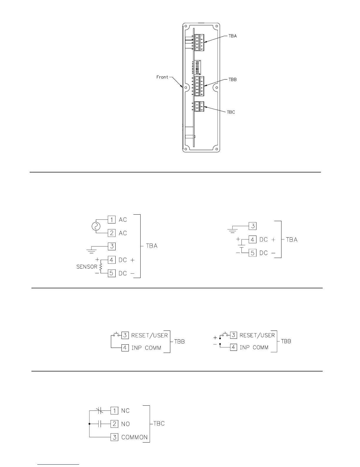
The power wiring is made via the 5 position terminal block (TBA) located
inside unit (right side).
Do not power unit from both AC & DC at the same time.
3.1 POWER WIRING
DC Power
Terminal 3: Earth Ground
Terminal 4: +DC Input
Terminal 5: DC Common
AC Power
Terminal 1: VAC
Terminal 2: VAC
Terminal 3: Earth Ground
Terminal 4: +DC Out
Terminal 5: DC Common
3.3 SETPOINT (OUTPUT) WIRING
The setpoint relay uses a three position terminal block (TBC) located on the
left side of the LD2 model, and on the right side for the LD4 model.
Terminal 1: NC
Terminal 2: NO
Terminal 3: Relay Common
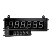
WIRING OVERVIEW
Electrical connections are made via pluggable terminal blocks
located inside the meter. All conductors should conform to the
meter's voltage and current ratings. All cabling should conform
to appropriate standards of good installation, local codes and
regulations. It is recommended that the power supplied to the
meter (DC or AC) be protected by a fuse or circuit breaker. When
wiring the meter, compare the numbers on the label on the back
of the meter case against those shown in wiring drawings for
proper wire position. Strip the wire, leaving approximately 0.4"
(10 mm) bare lead exposed (stranded wires should be tinned with
solder.) Insert the lead under the correct screw clamp terminal
and tighten until the wire is secure. (Pull wire to verify tightness.)
Each terminal can accept up to one #14 AWG (2.55 mm) wire,
two #18 AWG (1.02 mm), or four #20 AWG (0.61 mm).
RIGHT SIDE VIEW
Model LD4T06P0 is shown.
The LD2T06P0 unit has TBC
located on the left side.
3.2 USER INPUT WIRING
The Reset/User Input is always Terminal 3 and Input Common is always
terminal 4 of TBB located inside the unit (right side).
Terminal 3: Reset/User Input
Terminal 4: Input Common
Sinking Logic Sourcing Logic
DIP switch 6 OFF
DIP switch 6 ON