4
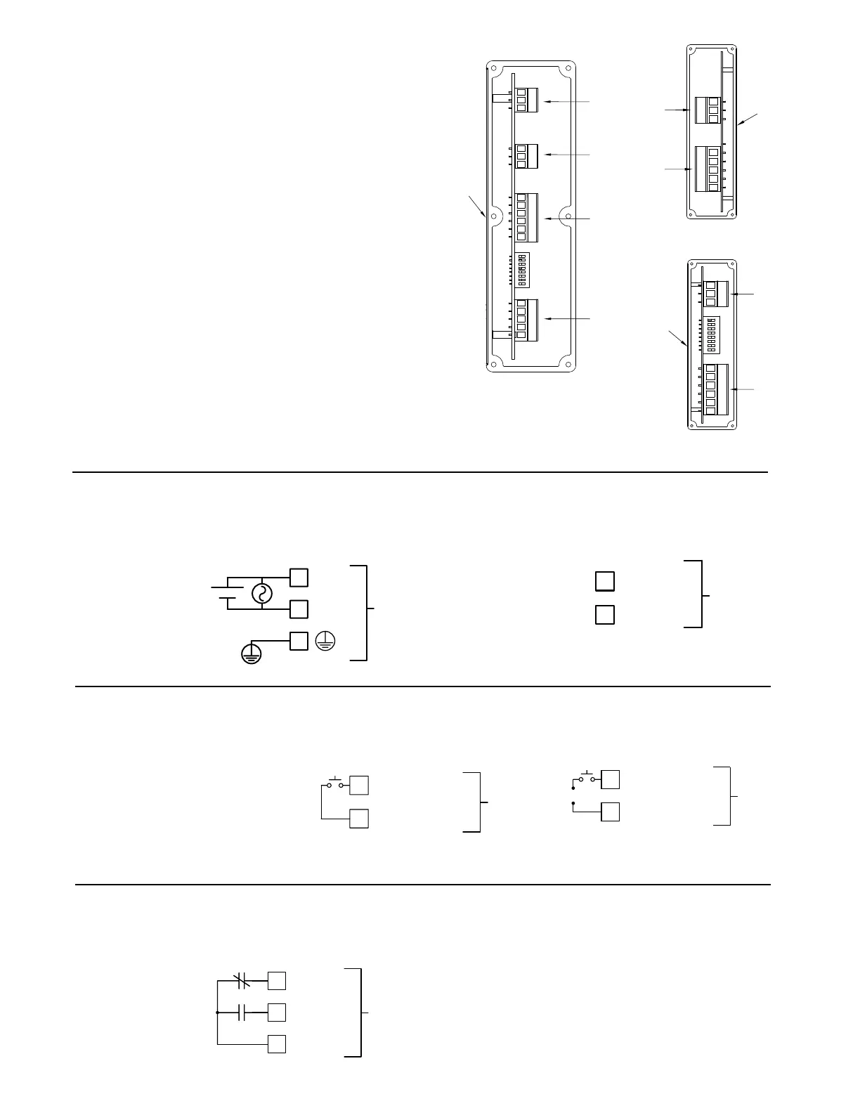
3.3 SETPOINT (OUTPUT) WIRING
The setpoint relay uses a three position terminal block (TBC) located on the
left side of the LD2 model, and on the right side for the LD4 model.
Terminal 1: Normally Closed
Terminal 2: Normally Open
Terminal 3: Relay Common
1
NC
COMMON
3
2
NO
TBC
WIRING OVERVIEW
Electrical connections are made via pluggable terminal blocks located inside
the meter. All conductors should conform to the meter's voltage and current
ratings. All cabling should conform to appropriate standards of good installation,
local codes and regulations. It is recommended that the power supplied to the
meter (DC or AC) be protected by a fuse or circuit breaker. When wiring the
meter, compare the numbers on the label on the back of the meter case against
those shown in wiring drawings for proper wire position. Strip the wire,
according to the terminal block specifications. Insert the lead under the correct
screw clamp terminal and tighten until the wire is secure. (Pull wire to verify
tightness.)
WIRING CONNECTIONS
Internal removable terminal blocks are used for power and signal wiring.
Access to terminal blocks is through conduit fittings. Remove end plates with
¼" nut driver. For LD4 versions, all wiring is on right side of unit. For LD2
versions, power and input wiring connections are on the right side and the relay
and serial connections are on the left side.
Feed the wire stripped end of cable(s) through the cord grip(s). Un-plug the
internal removable terminal blocks and wire appropriately.
Plug in the terminal blocks, connect the drain wire from shielded cable(s) to
the screw on the side plate for proper grounding, and slide the end plate(s) into
place and tighten to case. Hand tighten all cap screws and then tighten the cap
screws at the opposite corner diagonally.
Important: To maintain the Type 4X/IP65 specification, the cord grip must be
tightened around a cable with an outside diameter of 0.181" (4.6 mm) to
0.312" (7.9 mm). If the cord grip is unused, remove it and replace with the
LD cord grip plug (part # LDPLUG00). The LDPLUG00 must be ordered
separately.
DIP switch 6 OFF
DIP switch 6 ON
The power wiring is made via the 3 position terminal block (TBA) located
inside the unit (right side). The DC out power is located on TBB (right side).
3.1 POWER WIRING
COMM
+ EXC
6
4
TBB
DC Out Power
Terminal 4: + 24 VDC OUT
Terminal 6: User Common
Power
Terminal 1: VAC/DC +
Terminal 2: VAC/DC -
Terminal 3: Protective Conductor
Terminal
1
2
L(+)
N(-)
3
TBA
+
-
3.2 RESET/USER INPUT WIRING
The Reset/User Input is located on the right side
Terminal 5: Reset/User Input
Terminal 6: User Common
RESET/USER
5
COMM
6
TBB
RESET/USER
COMM
6
5
TBB
-
Sinking Logic Sourcing Logic
Front
4 53
TBD
1 2
TBC
TBB
321
TBA
8
1
2 63 541
31 2
321
5
431 2
TBD
TBC
Front
TBB
Front
654321
8
1
TBA
321
LD4
LD2 Right Side
LD2 Left Side
 Loading...
