1
2
3
4
Use the input cable ( to connect
headphone monitor output on your
mixing desk.
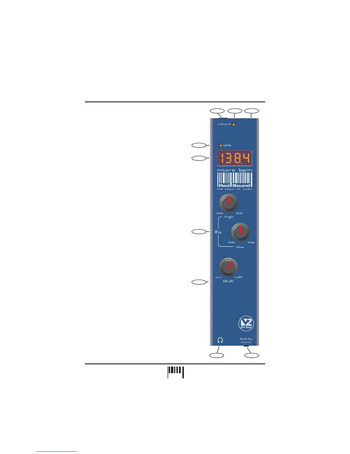
Use this bi-colour red/green LED to maintain the
ideal input level. See ‘ Input
Level ’ on page 3.
Connect the output plug of the AC adaptor
supplied with the MICRO BPM to this socket.
This LED flashes on each beat to visually indicate
the tempo.
AUDIO INPUT - Connector
POWER IN - Connector
BEAT - Indicator
supplied) this
socket to the
Setting the correct
(or optional Rechargeable Battery Pack)
The four digit BPM reading from the monitored
audio signal will be displayed here.
The centre-click, High (6.5kHz) and Low (100Hz)
EQ controls can be used to cut or boost the audio
signal whenever adjustment is required.
This knob controls the output level to the
connected headphones.
Connect the plug from your headphones to this
6.3mm gold-plated socket.
Use this switch to monitor the audio signal in
stereo (up) or mono (down).
AUDIO INPUT LEVEL - Indicator
BPM - Display
EQUALIZATION - Rotary controls
LEVEL - Rotary control
HEADPHONE OUT - Connector
STEREO / MONO - Switch
5
6
7
8
9
2
4
5
1
6
7
8
9
FRONT PANEL CONTROLS AND
CONNECTORS
Here’s a quick guide to the controls and connectors
on the MICRO BPM.
FRONT PANEL/CONNECTORS
3
+
+
-
-
/
2
PAGE