MIDI OUT
13 8 413 8 4
MIDI CLOCK
BEAT 1
RESET
STOP
OKPULL PUSH
SYNC
bpm
TAP
NUDGE
PULL
BPM
UP
BPM
down
PUSH
POWER
www.redsound.com
INPUT
Red
Sound
the colour of music
micro sync
/
+/
-/
FRONT PANEL/CONNECTORS
1
2
3
Use the input cable ( to connect
booth/record or master output on
your mixing desk.
Use this bi-colour red/green LED to maintain the
ideal input level. See ‘ Input
Level ’on page 5.
Connect the output plug of the AC adaptor
supplied with the MICRO SYNC to this socket.
AUDIO INPUT - Connector
POWER IN - Connector
supplied) this
socket to the
Setting the correct
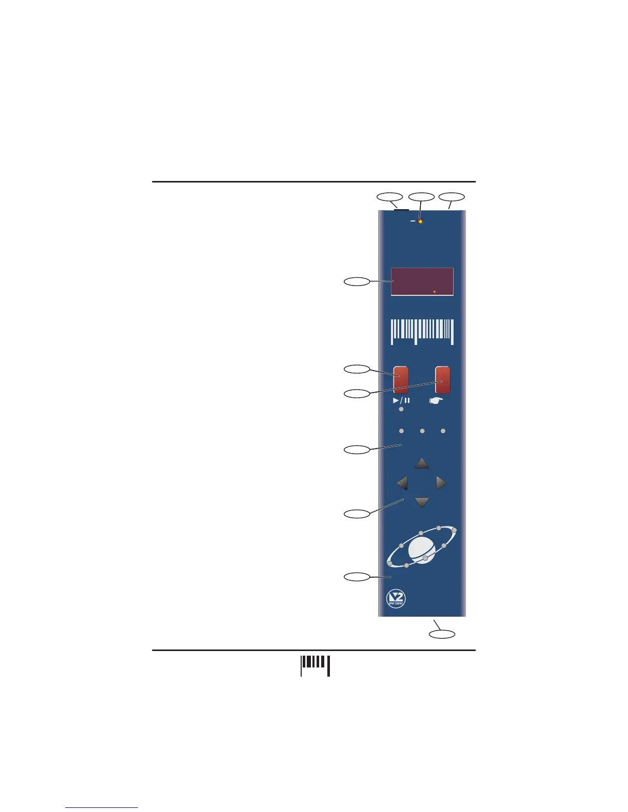
The four digit BPM reading of the audio signal will
be displayed here.
Press this button to run or pause the connected
MIDI sequencer. (Also sets the BPM range)
Tap this button to manually enter a BPM. Press
and hold the button to stop the MIDI clock and
reset the BPM display.
This 3-way indicator shows any synchronisation
adjustments.
Use this 4-way keypad to manually edit the BPM
reading or adjust the audio/MIDI sync point - see
page 8. (Also used for parameter editing)
This 8 indicator display ‘rotates’ at the BPM rate
when the MICRO SYNC’s MIDI clock is running.
Use a suitable MIDI cable to connect this socket to
the MIDI IN connector on your sequencer.
AUDIO INPUT LEVEL - Indicator
BPM - Display
RUN/PAUSE - Button
TAP (RESET/STOP) - Button
SYNCHRONISATION - Display
NUDGE - 4 Buttons
MIDI CLOCK - Display
MIDI OUT - Connector
4
5
6
7
8
9
10
FRONT PANEL CONTROLS AND
CONNECTORS
Here’s a quick guide to the controls and connectors
on the MICRO SYNC.
3
1
10
2
5
9
7
8
6
4
2
PAGE