2
SPECIFICATIONS
1. POWER: 24 VDC ± 10%
400 mA min. (1 module)
5 Amps max. (16 modules + Expansion Card)
Must use Class 2 or SELV rated power supply.
2. COMMUNICATIONS:
USB/PG Port: Adheres to USB specification 1.1. Device only using Type B
connection.
Serial Ports: Format and Baud Rates for each port are individually software
programmable up to 115,200 baud.
RS232/PG Port: RS232 port via RJ12
COMMS Ports: RS422/485 port via RJ45, and RS232 port via RJ12
DH485 TXEN: Transmit enable; open collector, V
OH
= 15 VDC,
V
OL
= 0.5 V @ 25 mA max.
Note: For additional information on the communications or signal common
and connections to earth ground please see the “Connecting to Earth
Ground” in the section “Installing and Powering the CSMSTRSX.”
Ethernet Port: 10 BASE-T / 100 BASE-TX
RJ45 jack is wired as a NIC (Network Interface Card).
3. LEDs:
STS – Status LED indicates condition of master.
TX/RX – Transmit/Receive LEDs show serial activity.
Ethernet – Link and activity LEDs.
CF – CompactFlash LED indicates card status and read/write activity
4. MEMORY:
On-board User Memory: 4 Mbytes of non-volatile Flash memory.
On-board SDRAM:
CSMSTRSX: 2 Mbytes
CSMSTRGT: 8 Mbytes
Memory Card: CompactFlash Type II slot for Type I and Type II cards.
5. REAL-TIME CLOCK: Typical accuracy is less than one minute per month
drift. Crimson 2.0’s SNTP facility allows synchronization with external servers.
Battery: Lithium Coin Cell. Typical lifetime of 10 years at 25 ºC.
A “Battery Low” system variable is available so that the programmer can
choose specific action(s) to occur when the battery voltage drops below
its nominal voltage.
6. ENVIRONMENTAL CONDITIONS:
Operating Temperature Range: 0 to 50°C
Storage Temperature Range: -30 to +70°C
Operating and Storage Humidity: 80% max relative humidity,
non-condensing, from 0 to 50°C
Altitude: Up to 2000 meters
7. CONSTRUCTION: Case body is burgundy high impact plastic and
stainless steel. Installation Category I, Pollution Degree 2.
8. POWER CONNECTION: Removable wire clamp screw terminal block.
Wire Gage Capacity: 24 AWG to 12 AWG
Torque: 4.45 to 5.34 in/lb (0.5 to 0.6 N-m)
9. MOUNTING: Snaps onto standard DIN style top hat (T) profile mounting
rails according to EN50022 -35 x 7.5 and -35 x 15.
10. CERTIFICATIONS AND COMPLIANCES:
SAFETY
IEC 61010-1, EN 61010-1: Safety requirements for electrical equipment
for measurement, control, and laboratory use, Part 1.
ELECTROMAGNETIC COMPATIBILITY
Emissions and Immunity to EN 61326: Electrical Equipment for
Measurement, Control and Laboratory use.
Notes:
1. Criterion A: Normal operation within specified limits.
2. This device was designed for installation in an enclosure. To avoid
electrostatic discharge to the unit in environments with static levels above
4 kV precautions should be taken when the device is mounted outside an
enclosure. When working in an enclosure (ex. making adjustments, setting
jumpers etc.) typical anti-static precautions should be observed before
touching the unit.
11. WEIGHT: 15.1 oz (456.4 g)
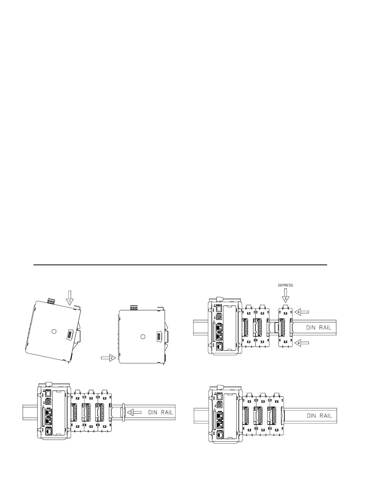
HARDWARE
INSTALLATION
Figure 1 - Attach CSMSTR Master To DIN Rail
Figure 3 - Attach Termination Plug*
* Supplied with CSMSTR Master Module.
Figure 2 - Attach Slave Bases To DIN Rail
Figure 4 - Installation Complete
Immunity to Industrial Locations:
Electrostatic discharge EN 61000-4-2
Criterion A
2
4 kV contact discharge
8 kV air discharge
Electromagnetic RF fields EN 61000-4-3 Criterion A
10 V/m
Fast transients (burst) EN 61000-4-4 Criterion A
2 kV power
2 kV signal
Surge EN 61000-4-5 Criterion A
1kV L-L,2 kV L&N-E power
RF conducted interference EN 61000-4-6 Criterion A
3 V/rms
Emissions:
Emissions EN 55011 Class A
 Loading...