9
INSTALLATION
Attachment Methods Using Straps
Method 1
Use(4)#8x3/4sheetmetalscrewsforeachstrap.
The straps should be vertical against the Air Handler sides
and not pull away from the Air Handler sides.
Method 2
Fold all straps under the Air Handler and secure with (4)
#8x3/4sheetmetalscrews(2screwsatthesideand
2 screws at the bottom. (Care must be taken not to drive
the screw through the coil.)
DUCT CONNECTIONS
Supply Duct
The supply ductwork must be attached to the outside of the
angeontheairdischargeendofunit.Flexibleconnectors
may be used if desired.
Return Duct
The return ductwork should be attached to the air return
side (bottom or side) of unit using sheet metal screws or
other fasteners.
For side return air inlet installation, see Figures 3 and 4.
FILTER INSTALLATION
Externallterrackanda1inchdisposablelterare
standard on all models. Refer to the Specifications
section for dimensions.
AIR DISTRIBUTION SYSTEM
Existing Ductwork
It is the responsibility of the installer to inspect all
previously installed air distribution system to determine
its suitability for the new heating and/or cooling system.
Existingductworkmayhavetobemodiedand/orinsulated
to provide satisfactory air distribution.
Ductwork Installation
Connect the supply-air duct over the outside of 3/4-in.
flange on the unit’s discharge side. Secure the duct to the
flange with proper fasteners for the type of duct used.
Support the duct independently.
Useexibleconnectors(ifdesiredbetweentheductwork
and the unit to prevent transmission of vibration.
Use insulation with vapor barrier for ductwork passing
through unconditioned spaces.
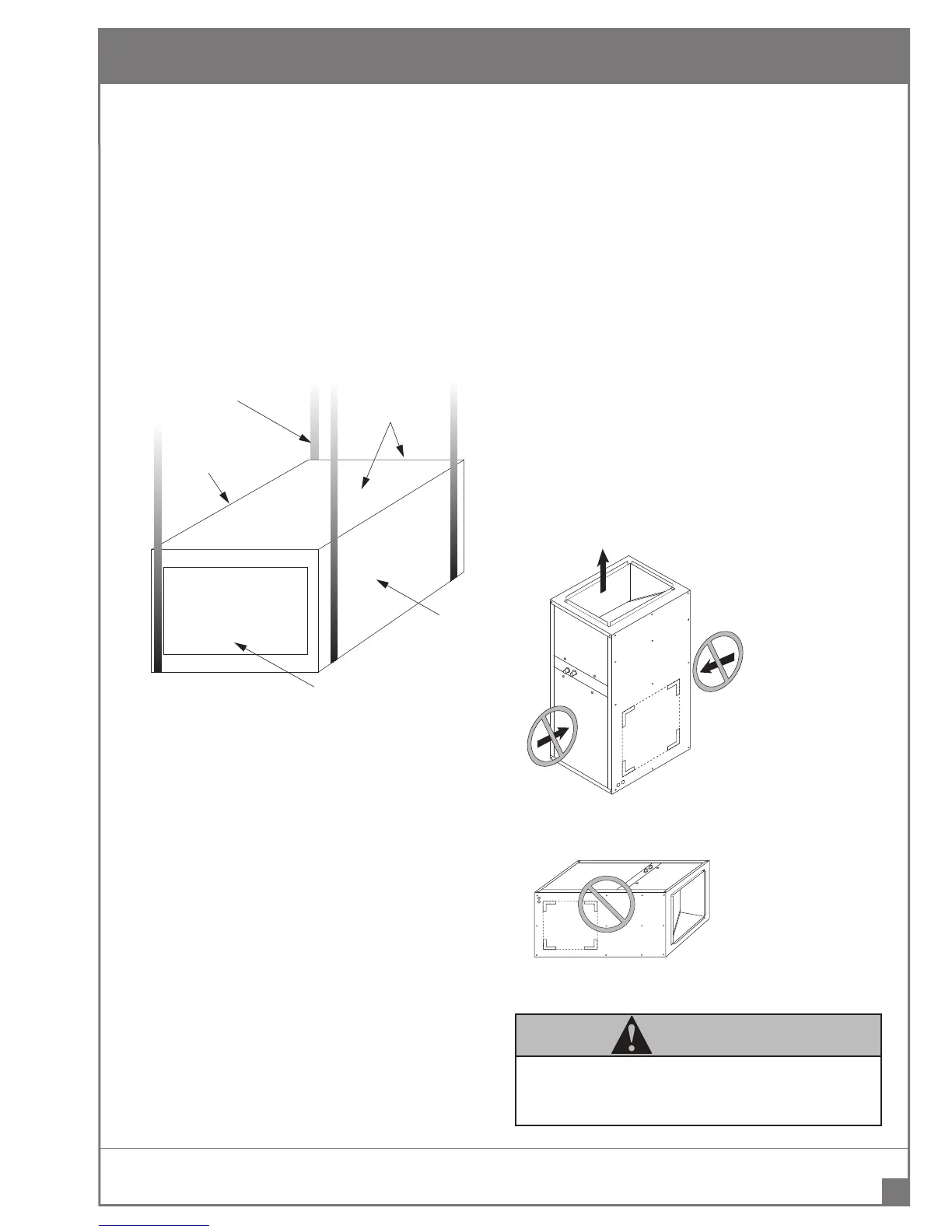
PROHIBITED INSTALLATIONS
REDZONE
TM
DVS SERIES AIR HANDLER MANUAL
DOOR
ASSEMBLY
1 INCH x 22 GAUGE
GALVANIZED STRAPS
TYPICAL FOR 4 STRAPS
SUPPLY AIR OPENING
BACK
COIL AREA
RETURN AIR
OPENING
FIGURE 7 Horizontal Unit Suspension with Straps
FRONT
BACK
FIGURE 8
The air inlet is not allowed to
be at the front or back of the
Air Handler.
FIGURE 9
Do not position the Air Handler
on its back or with its face
down.
WARNING
Multiple Air Handlers configured for installation with a
single Tankless Water Heater is prohibited.
 Loading...