12
11. Setting up the Receiver
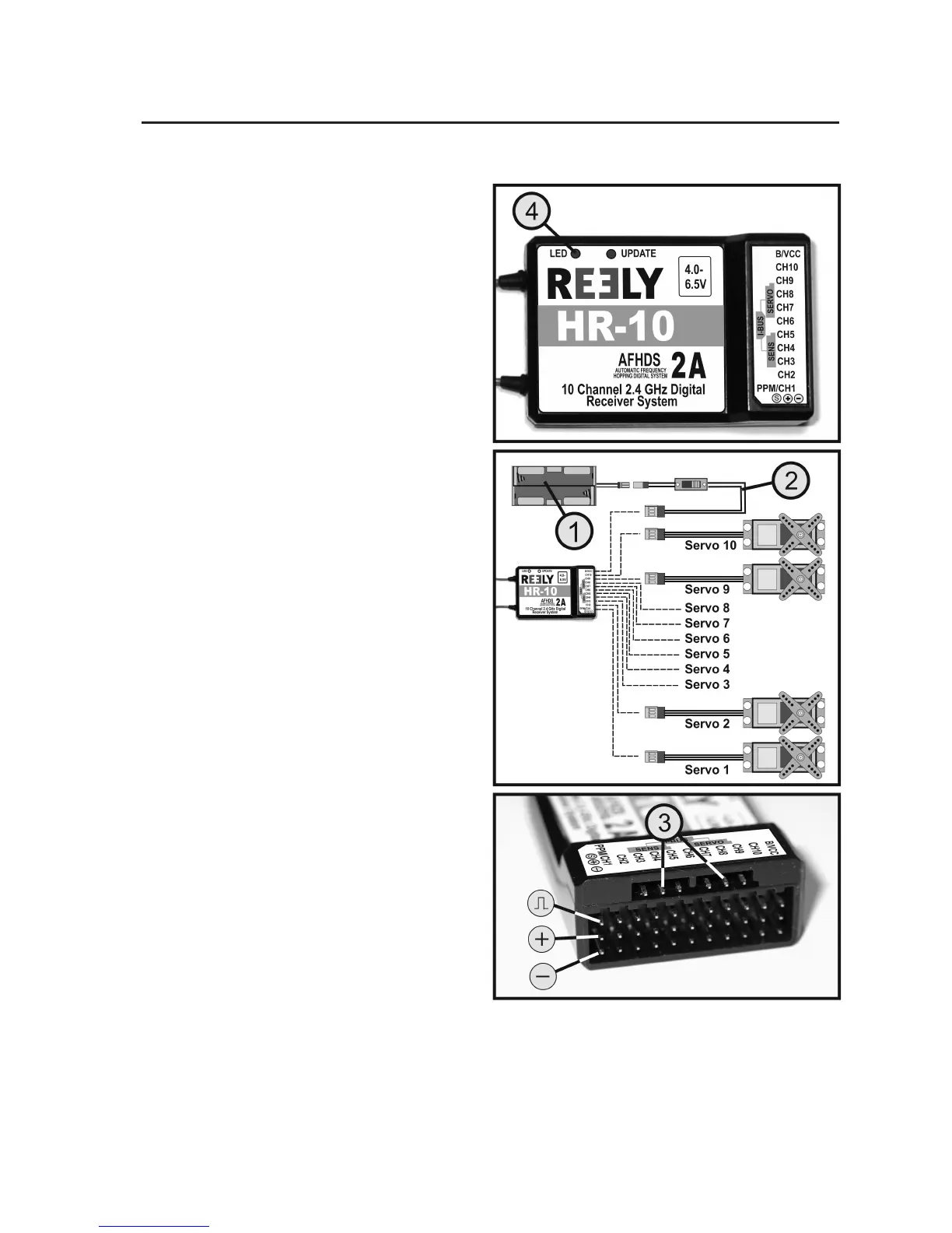
a) Connecting the Receiver
The receiver offers connection options for up to 10 ser-
vos (channels 1 to 10 correspond to the receiver outputs
"CH1" to "CH10"). The servos can also be replaced by
motor/speed controllers or switching elements.
If the remote control is used for a plane/helicopter model,
the receiver outputs "CH1" to "CH4" are assigned to the
following functions:
"CH1" = Aileron/roll servo (AIL*)
"CH2" = Elevator/nod servo (ELE*)
"CH3" = Throttle servo, ight/speed controller (THR*)
"CH4" = Rudder/tail servo (RUD*)
* The three letters in brackets correspond to the Eng-
lish abbreviations for the function designations. The
reverse switches for channels 1 - 4 (see gure 1, item
11) are also labelled with these abbreviations.
At the "B/VCC" connection, a battery box (1) or a receiv-
er battery with switch cable (2) is connected if no ight
controller with BEC switch is used.
If 2 servos are needed for a steering function (e.g. the
aileron steering at plane models), the servos must be
connected via a V-cable to the receiver output "CH1".
For the ailerons to deect alternatingly, the servos must
be installed in the wing mirror-inverted.
The receiver also offers a connection option for I-Bus-
capable servos and sensors (see gure 5, item 3). In
combination with the remote control system "HT-10",
these connections are, however, not assigned or used.
Figure 5