To change Alarm Relay Operation:
1. Unplug pump
2. Move DIP switch positions to
3. Plug pump in
4. Wait for one green LED blink
5. Move DIP switch positions to
6. Wait for one red LED blink
7. Reset DIP switch positions to
8. Wait for one green LED blink
9. Unplug pump
10. Set the DIP switches back to the desired capacity
configuration. (Low, Medium-Low, Medium-High, High)
11. Plug Pump in and check that power up LED sequence
matches the desired alarm relay operation
12. Done.
To reset default alarm relay operation repeat
steps 1 thru 11.
4
5
View installation video at www.condensate-pumps.com
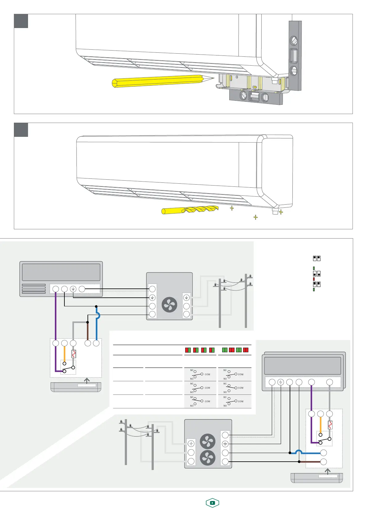
Evaporator Unit (Indoor)
NC NO
COM
COM
NC
NO
(typical) Data
Condenser Unit (Outdoor)
100-240vac~
Blue
Brown
Grey
Replaceable
Fuse 10A
**Orange
Violet
Alarm
Relay
Neutral
Earth
NL
N
L
3
N
L
NL 3
Condensate Pump
When Indoor Evaporator Unit is powered from the Outdoor Condenser Unit
(typical) Data
VRF Condenser Unit
(Outdoor)
100-240vac~
Neutral
Earth
Evaporator Units (Indoor)
N
L
3
When Multi-Split System is installed
NC
COM
NC
NO
Grey
Blue
Brown
Replaceable
Fuse 10A
**Orange
Violet
Alarm
Relay
Condensate Pump
Safety Circuit
L
NO
COM
N
N
L
N L3
Power Up LED Sequence
Pump Status Condensate Level
Default
Operation
Fail-Safe
Operation
Unpowered N/A
Powered Below Alarm Level
Powered Alarm-Activated
Alarm Relay Operation Table
**Orange:
To use fail-safe operation.
1. Remove the violet wire from indoor live.
2. Connect the orange wire to indoor live.
3. Change alarm relay to fail-safe operation.
**Orange:
To use fail-safe
operation.
1. Remove the violet wire
from indoor live.
2. Connect the orange
wire to indoor live.
3. Change alarm relay to
fail-safe operation.

 Loading...