Theory
of
Operation
Lexicon
Front
Panel,
Foot
Switches,
MID!
I/O,
EEPROM
I/O
Registers
There
are two
output registers,
U6
(74LS374)
and U5
(74HC374)
and
two
input
registers,
U4
(74HC541)
and
U3
(74HC541).
Output
Register
1
and
Input Register!
(U6
and
U4)
share the same
memory
space.
The
outputs and
inputs
are separately
decoded using the read and
write
signals. The
same
is
true
for
Output Register 2 and Input Register
2
(U5
and
U3).
0/P
Registers
OUT!
{U6)drivesthe24display LED
segments.
The three digits of
the display
are time-multiplexed.
Approximately every 6
ms, two digits
are turned
off
and
the other digit
is
turned on. To
drive
the
middle digit
(LSD),
the Z80
writes
to
0UT2
(U5)
,
a 0
to
pin
3,
and
a
1
to
pin
1
8
and
1 7. This turns on
Q3
and turns
off
Q2 and
Q5.
Q3’s
collector sources current into
the common
anode of
the
middle digit
on the display
board.
At
the
same
time, the
Z80
writes
O’s to
the
appropriate
segment
outputs
of
U6.
U6
must
be
an LS part
because an
HC
part
can’t
sink
enough
current
to
drive
a
multiplexed display.
Each
output of
U6
has
a
270 n
series resistor
to current
limit
the
LEDs
on the display
board.
As an HC374
can
directly drive
a
non-multiplexed
LED,
U5
directly drives
the
input
level
indicator
LED (D6). D6
is
a
bicolor
LED,
which
can switch
between
red and green.
R11
,
R1
2,
and
R34
are
used
to
current limitthe
input level LED
and provide
equal intensity
for
both
colors.
The RED/
and
GRN/
signals
work
together
to
select
color.
If GRN/
is
high
and
RED/
is
low,
the
level
LED
lights
red.
If
GRN/
is
low
and
RED/
is
high,
the
level LED lights
green.
Note the
output registers
are disabled
(DIPLAYEN/)
on reset
so
the display
will
be
blank
when
the
Z80
is not
running.
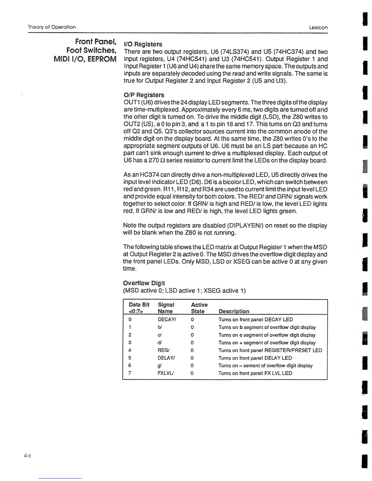
The following
table
shows
the
LED matrix
at Output
Register
1 when
the
MSD
at Output Register 2
is active
0.
The
MSD
drives
the
overflow
digit
display
and
the
front
panel
LEDs. Only MSD, LSD
or XSEG can
be
active
0 at
any
given
time.
Overflow Digit
(MSD
active
0;
LSD
active
1
;
XSEG active
1)
Data
Bit
<0:7>
Signal
Mame
Active
State Description
0
DECAY/
0 Turns on front panel DECAY
LED
1
b/
0 Turns on b
segment of
overflow
digit
display
2 cf 0
Turns on c segment
of
overflow digit display
3
d/
0 Turns on + segment
of overflow digit display
4
REG/ 0
Turns
on
front
panel REGISTER/PRESET
LED
5 DELAY/
0 Turns on front panel DELAY LED
6
g/
0
Turns
on
~
sement
of overflow
digit display
7
FXLVL/
0 Turns on front panel FX LVL LED
4-6
 Loading...